APPROACH 
TEST AND CHARGE METHOD
65ºF (18.3ºC) and Above
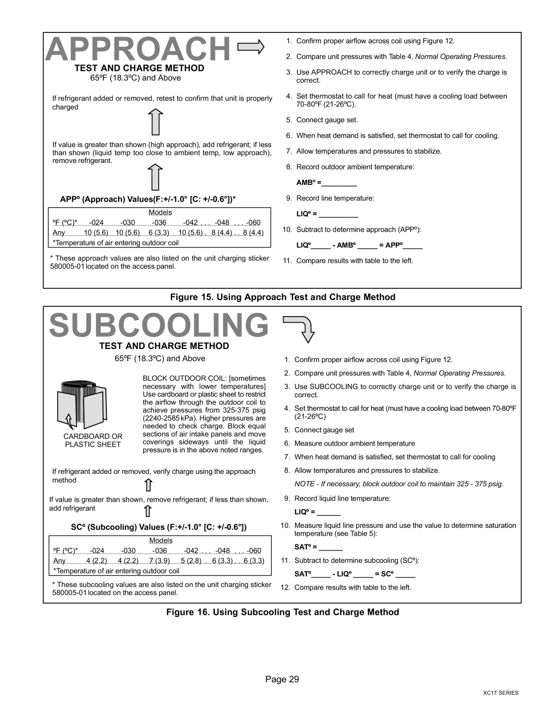
If refrigerant added or removed, retest to confirm that unit is properly charged
If value is greater than shown (high approach), add refrigerant; if less than shown (liquid temp too close to ambient temp, low approach), remove refrigerant.
APPº (Approach) Values(F:+/−1.0° [C: +/−0.6°])*
|
|
| Models |
|
|
ºF (ºC)* | −024 | −030 | −036 | −042 . . . −048 . . . −060 |
|
Any | 10 (5.6) | 10 (5.6) | 6 (3.3) | 10 (5.6) . 8 (4.4) . . 8 (4.4) | |
*Temperature of air entering outdoor coil
*These approach values are also listed on the unit charging sticker 580005−01 located on the access panel.
1.Confirm proper airflow across coil using Figure 12.
2.Compare unit pressures with Table 4, Normal Operating Pressures.
3.Use APPROACH to correctly charge unit or to verify the charge is correct.
4.Set thermostat to call for heat (must have a cooling load between
5.Connect gauge set.
6.When heat demand is satisfied, set thermostat to call for cooling.
7.Allow temperatures and pressures to stabilize.
8.Record outdoor ambient temperature: AMBº =_________
9.Record line temperature: LIQº = __________
10.Subtract to determine approach (APPº): LIQº_____ − AMBº _____ = APPº_____
11.Compare results with table to the left.
Figure 15. Using Approach Test and Charge Method
SUBCOOLING
TEST AND CHARGE METHOD
65ºF (18.3ºC) and Above
1. | Confirm proper airflow across coil using Figure 12. |
2. | Compare unit pressures with Table 4, Normal Operating Pressures. |
CARDBOARD OR PLASTIC SHEET
BLOCK OUTDOOR COIL: [sometimes necessary with lower temperatures] Use cardboard or plastic sheet to restrict the airflow through the outdoor coil to achieve pressures from 325−375 psig (2240−2585 kPa). Higher pressures are needed to check charge. Block equal sections of air intake panels and move coverings sideways until the liquid pressure is in the above noted ranges.
3. | Use SUBCOOLING to correctly charge unit or to verify the charge is |
| correct. |
4. | Set thermostat to call for heat (must have a cooling load between |
| (21−26ºC) |
5. | Connect gauge set |
6. | Measure outdoor ambient temperature |
7. | When heat demand is satisfied, set thermostat to call for cooling |
If refrigerant added or removed, verify charge using the approach method![]()
If value is greater than shown, remove refrigerant; if less than shown, add refrigerant![]()
SCº (Subcooling) Values (F:+/−1.0° [C: +/−0.6°])
|
|
| Models |
|
|
ºF (ºC)* | −024 | −030 | −036 | −042 . . . −048 . . . −060 |
|
Any | 4 (2.2) | 4 (2.2) | 7 (3.9) | 5 (2.8) . 6 (3.3) . . 6 (3.3) | |
*Temperature of air entering outdoor coil
*These subcooling values are also listed on the unit charging sticker 580005−01 located on the access panel.
8. | Allow temperatures and pressures to stabilize. |
| NOTE − If necessary, block outdoor coil to maintain 325 − 375 psig. |
9. | Record liquid line temperature: |
| LIQº = ______ |
10. | Measure liquid line pressure and use the value to determine saturation |
| temperature (see Table 5): |
| SATº = ______ |
11. | Subtract to determine subcooling (SCº): |
| SATº_____ − LIQº _____ = SCº _____ |
12. | Compare results with table to the left. |
Figure 16. Using Subcooling Test and Charge Method
Page 29
XC17 SERIES
