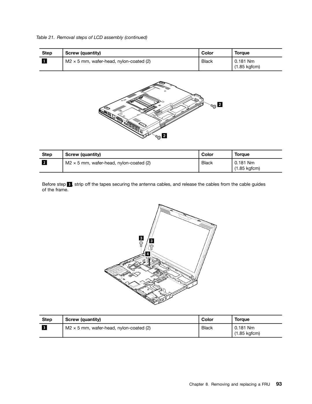
Table 21. Removal steps of LCD assembly (continued)
| Step | Screw (quantity) | Color | Torque | |
|
|
|
|
|
|
|
|
| M2 × 5 mm, | Black | 0.181 Nm |
| 1 |
| |||
|
|
|
|
| (1.85 kgfcm) |
|
|
|
|
|
|
2
2
| Step | Screw (quantity) | Color | Torque | |
|
|
|
|
|
|
|
|
| M2 × 5 mm, | Black | 0.181 Nm |
| 2 |
| |||
|
|
|
|
| (1.85 kgfcm) |
|
|
|
|
|
|
Before step 3 , strip off the tapes securing the antenna cables, and release the cables from the cable guides of the frame.
| Step | Screw (quantity) | Color | Torque | |
|
|
|
|
|
|
|
|
| M2 × 5 mm, | Black | 0.181 Nm |
| 3 |
| |||
|
|
|
|
| (1.85 kgfcm) |
|
|
|
|
|
|
Chapter 8. Removing and replacing a FRU 93