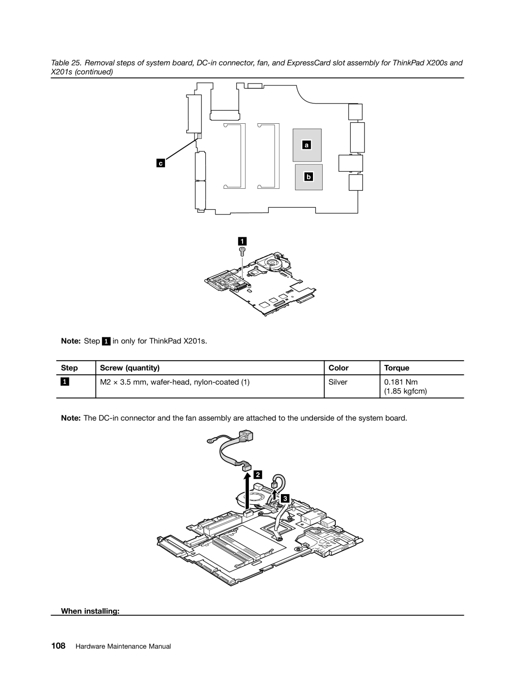
Table 25. Removal steps of system board,
c
1
Note: Step 1 in only for ThinkPad X201s.
a
b
| Step | Screw (quantity) | Color | Torque | |
|
|
|
|
|
|
|
|
| M2 × 3.5 mm, | Silver | 0.181 Nm |
| 1 |
| |||
|
|
|
|
| (1.85 kgfcm) |
|
|
|
|
|
|
Note: The
2
![]()
![]() 3
3![]()
![]()
Table 25. Removal steps of system board,
c
1
Note: Step 1 in only for ThinkPad X201s.
a
b
| Step | Screw (quantity) | Color | Torque | |
|
|
|
|
|
|
|
|
| M2 × 3.5 mm, | Silver | 0.181 Nm |
| 1 |
| |||
|
|
|
|
| (1.85 kgfcm) |
|
|
|
|
|
|
Note: The
2
![]()
![]() 3
3![]()
![]()