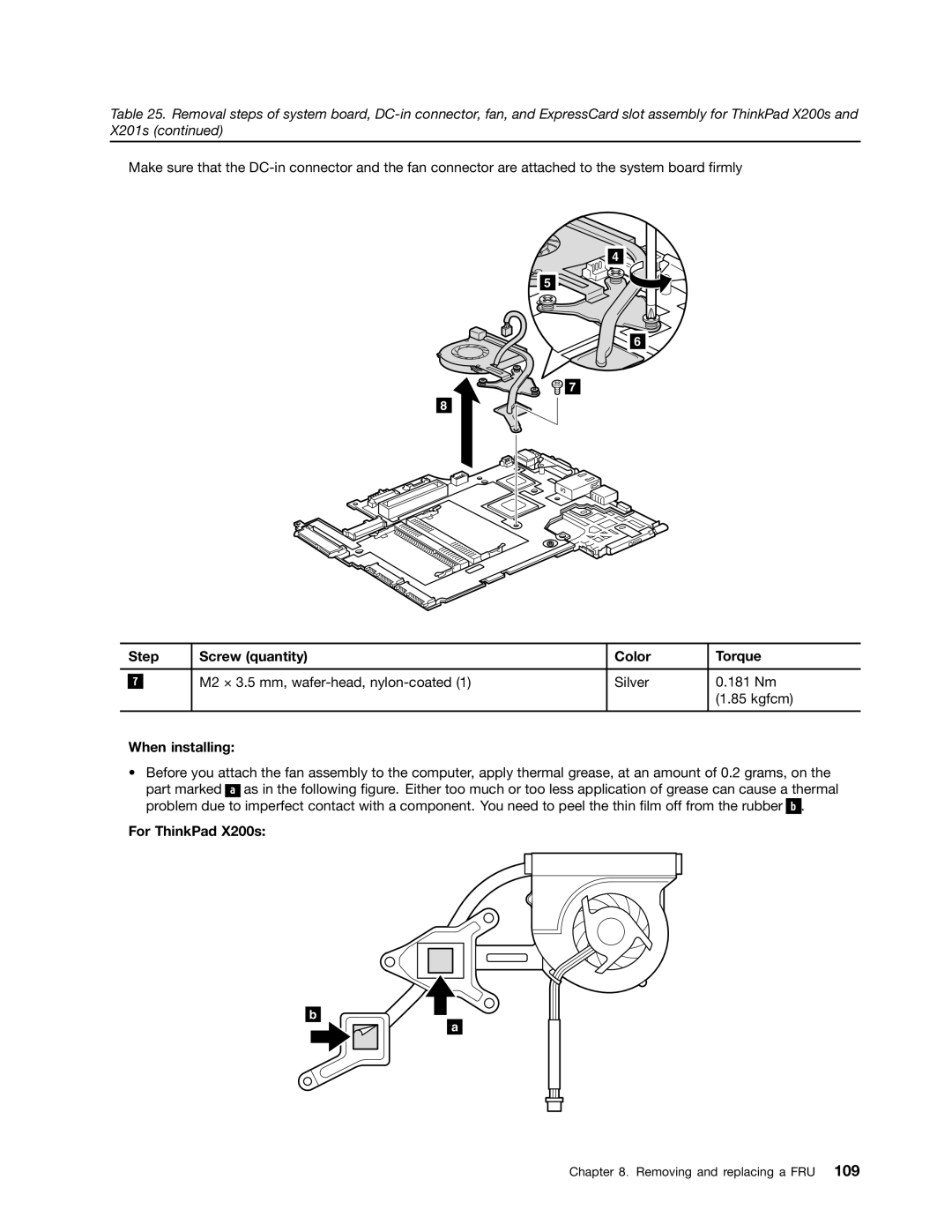
Table 25. Removal steps of system board,
Make sure that the
4![]()
5 ![]()
![]()
6
![]()
![]()
![]()
![]()
![]() 7 8
7 8 ![]()
![]()
![]()
![]()
| Step | Screw (quantity) | Color | Torque | |
|
|
|
|
|
|
|
|
| M2 × 3.5 mm, | Silver | 0.181 Nm |
| 7 |
| |||
|
|
|
|
| (1.85 kgfcm) |
|
|
|
|
|
|
When installing:
•Before you attach the fan assembly to the computer, apply thermal grease, at an amount of 0.2 grams, on the
part marked ![]()
![]()
![]() as in the following figure. Either too much or too less application of grease can cause a thermal problem due to imperfect contact with a component. You need to peel the thin film off from the rubber b .
as in the following figure. Either too much or too less application of grease can cause a thermal problem due to imperfect contact with a component. You need to peel the thin film off from the rubber b .
For ThinkPad X200s:
b
a
Chapter 8. Removing and replacing a FRU 109