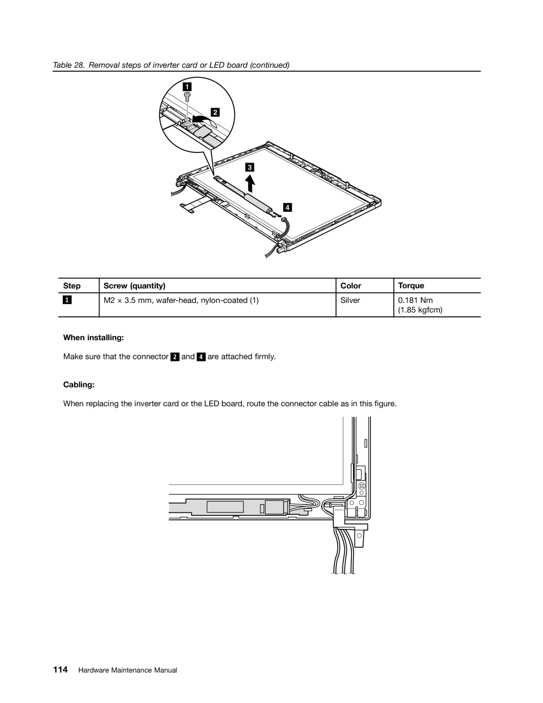
Table 28. Removal steps of inverter card or LED board (continued)
1
2
3
4
| Step | Screw (quantity) | Color | Torque | |
|
|
|
|
|
|
|
|
| M2 × 3.5 mm, | Silver | 0.181 Nm |
| 1 |
| |||
|
|
|
|
| (1.85 kgfcm) |
|
|
|
|
|
|
When installing:
Make sure that the connector
2
and
4
are attached firmly.
Cabling:
When replacing the inverter card or the LED board, route the connector cable as in this figure.