ThinkServer RD120 Types 6444, 6445, 6446, and
Installation Guide
Page
ThinkServer RD120 Types 6444, 6445, 6446, and
First Edition October Copyright Lenovo
Chapter 3. Server controls, LEDs, and power
Contents
Chapter 4. Configuring the server
Appendix A. Getting help and technical assistance
Safety
Each caution and danger statement in this document is labeled with a number. This number is used to cross reference an English-language caution or danger statement with translated versions of the caution or danger statement in the Safety Information document
Statement DANGER
Statement
Appareil A Laser de Classe
Class 1 Laser Product Laser Klasse Laser Klass Luokan 1 Laserlaite `
≥ 32 kg 70.5 lb
≥ 18 kg 39.7 lb
≥ 55 kg 121.2 lb
Statement
This server is suitable for use on an IT power-distribution system whose maximum phase-to-phase voltage is 240 V under any distribution fault condition
Chapter 1. Introduction
The Lenovo ThinkServer Documentation DVD
Hardware and software requirements
Notices and statements in this document
Features and specifications
Microprocessor
Table 1. Features and specifications
Major components of the server
Power backplane
Installation guidelines
Chapter 2. Installing optional devices
System reliability guidelines
Working inside the server with the power on
Removing the cover
Handling static-sensitive devices
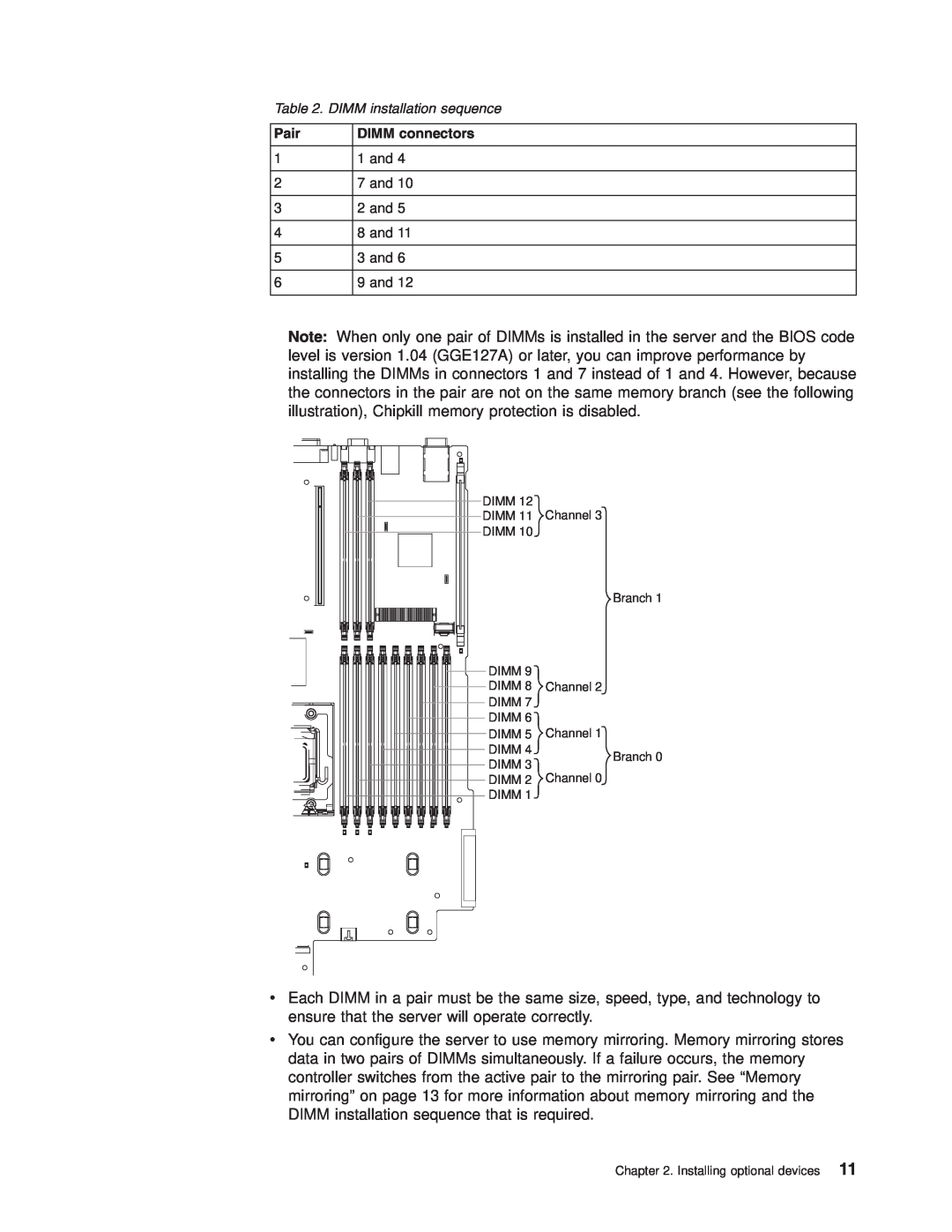
Installing a memory module
Pair
DIMM connectors
1 1 and 2 7 and 3 2 and 4 8 and 5 3 and 6 9 and
Page
Memory mirroring
1 1, 4, 7, and 2 2, 5, 8, and 3 3, 6, 9, and
Online-spare memory
Table 5. Online-spare DIMM configurations, basic scheme
In the configuration that you use, install the largest DIMMs first
3.5-inch drives
Installing a hard disk drive
2.5-inch drives
Installing a tape drive
Installing an additional microprocessor
Voltage regulator module
connector
Microprocessor socket dust cover
4. Remove the microprocessor air baffle
Note The microprocessor fits only one way on the socket
8. Install a heat sink on the microprocessor
Low-profile PCI Express adapter
Installing an adapter
PCI riser card
Release tabs
Access holes
Hard disk drive cable connector 4
Installing a Remote Supervisor Adapter II SlimLine
Hard disk drive cable connector 0
Battery
3. Remove the cover 4. Remove the PCI riser-card assembly
Replacing the ServeRAID SAS controller
Completing the installation
Connecting the cables
Installing the cover
Front view
Rear view
Updating the server configuration
If you have installed or removed a hard disk drive, see “Usingthe RAID configuration programs” on page 44 for information about reconfiguring the disk arrays
Page
Front view
Chapter 3. Server controls, LEDs, and power
System-error LED
Power-on LED
Power-control button
Hard disk drive activity LED
Chapter 3. Server controls, LEDs, and power
Rear view
Server power features
Turning off the server
Turning on the server
Page
Using the ThinkServer EasyStartup program
Chapter 4. Configuring the server
User Guide on the ThinkServer Documentation DVD
Page
Using the Configuration/Setup Utility program
Using ThinkServer EasyManage products
Configuring the Gigabit Ethernet controllers
Using the IBM ServeRAID Configuration Utility program
Using the RAID configuration programs
Starting the IBM ServeRAID Configuration Utility program
Using ServeRAID Manager
IBM ServeRAID Configuration Utility menu choices
Configuring the RAID controller
2. Click Express configuration
Viewing the configuration
2. Click Custom configuration
BIOS update and configuration
Using the baseboard management controller
Red Hat Enterprise Linux ES 4 configuration
Linux configuration
LILO configuration If you are using LILO, complete the following steps
Original /etc/lilo.conf contents
2. Run the lilo command to store and activate the LILO configuration
Original /boot/grub/grub.conf contents
Modified /boot/grub/grub.conf contents
SUSE SLES 9.0 configuration
Modified /boot/grub/menu.lst contents
Original /boot/grub/menu.lst contents
b. Add the following line before the first title line
c. Append the following text to the first title line
COM1 and that redirectbaudrate is set to
Microsoft Windows 2003 Standard Edition configuration
Installing the OSA SMBridge management utility program
3. Type mount/mnt/cdrom
3. Follow the prompts to complete the installation
Using the baseboard management controller utility programs
Page
Page
Diagnostic tools overview
Chapter 5. Solving problems
POST beep codes
v Diagnostics DVD
Other beep codes
problem found
POST error codes
POST
Failing device or
Symptom
EasyStartup problems
Table 8. ThinkServer EasyStartup DVD
Action
CD-RW/DVD drive problems
Troubleshooting tables
Hard disk drive problems
General problems
the Hardware Maintenance Manual
Intermittent problems
USB keyboard, mouse, or pointing-device problems
Hardware Maintenance Manual
Memory problems
LEDs” in the Hardware Maintenance Manual
Microprocessor problems
Monitor problems
Page
Power problems
Optional-device problems
Hardware Maintenance Manual
Serial port problems
Software problems
Video problems
Universal Serial Bus USB port problems
Light path diagnostics
Light path diagnostics LEDs
Diagnosing problems using light path diagnostics
the User Guide on the ThinkServer Documentation DVD for
Action
Appendix A. Getting help and technical assistance
Using the documentation
Before you call
Getting help and information from the World Wide Web
Calling for service
Purchasing additional services
Using other services
Lenovo product service
Appendix A. Getting help and technical assistance
Page
Lenovo United States, Inc 1009 Think Place - Building One
Appendix B. Notices
Morrisville, NC U.S.A Attention Lenovo Director of Licensing
Important notes
Trademarks
Appendix B. Notices
Waste electrical and electronic equipment WEEE notices
For the European Union
Battery return program
Electronic emissions notices
German Ordinance for Work gloss statement
Federal Communications Commission FCC statement
For California
Industry Canada Class A emission compliance statement
United Kingdom telecommunications safety requirement
Avis de conformité à la réglementation dIndustrie Canada
Australia and New Zealand Class A statement
Deutschland
Japanese Voluntary Control Council for Interference VCCI statement
Betriebsmittein
Das Gerät erfüllt die Schutzanforderungen nach EN 55024 und EN
Korean Class A warning statement
Taiwanese Class A warning statement Chinese Class A warning statement
Index A
See SAS
connectors
software problems
Index
Page
Page
1P P/N 46U0862
Part Number 46U0862 Printed in USA