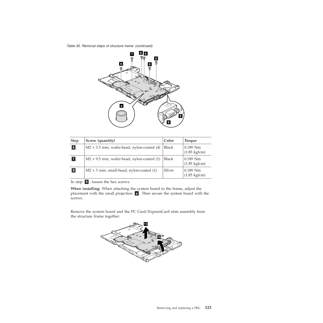
Table 30. Removal steps of structure frame (continued)
a
![]()
![]() 9 9
9 9
Step | Screw (quantity) | Color | Torque | |
|
|
|
|
|
| M2 | ⋅ 3.5 mm, | Black | 0.189 Nm |
|
|
|
| (1.85 kgfcm) |
|
|
|
|
|
| M2 | ⋅ 9.5 mm, | Black | 0.189 Nm |
|
|
|
| (1.85 kgfcm) |
|
|
|
|
|
| M2 | ⋅ 3 mm, | Silver | 0.189 Nm |
|
|
|
| (1.85 kgfcm) |
|
|
|
| |
In step | , loosen the hex screws. |
|
| |
When installing: When attaching the system board to the frame, adjust the placement with the small projection . Then secure the system board with the screws.
Remove the system board and the PC Card/ExpressCard slots assembly from the structure frame together.
11
10 |