Installation and Configuration
6.3.3PD-HDWR and PD-HDWR-MBS Terminal Block Connections
Conduit entry holes are provided on the rear and side of the box. Input and output wiring should not share the same conduit.
Table 1 Electrical requirements—PD-HDWR and PD-HDWR-MBS
Input Current | Recommended (Max.) | Recommended Wire | Maximum Wire | Terminal |
Rating | External Overcurrent | (including ground wire) | Accepted by | Tightening |
| Protection | (75°C copper wire) | Terminal Block | Torque |
24A | 30A | 10 AWG | 8 AWG | 20 |
|
|
|
|
|
The standard
N | L2 | L1 | N | L2 | L1 |
| OUTPUT |
| INPUT | 30A Max. Branch | |
|
| Overcurrent Protection | |||
|
|
|
| ||
|
|
| N |
|
|
|
|
| L2 |
|
|
|
| L1 | |||||
|
|
|
|
|
|
|
|
|
|
|
|
|
|
|
|
|
|
|
|
|
|
|
|
|
| 120 |
|
|
| 208 |
|
|
|
| |||||
|
|
|
|
|
|
|
|
|
|
|
| ||||||||
0 |
|
|
| 120 |
|
|
|
|
|
| |||||||||
|
|
|
|
|
|
|
|
|
|
|
|
|
|
|
|
|
| ||
|
|
|
|
|
|
|
|
|
|
|
|
|
|
|
|
|
| ||
|
|
|
|
|
|
|
|
|
|
|
|
| or 240 |
|
| ||||
|
|
|
|
|
|
|
|
|
|
|
|
| |||||||
Output to Load - See Note 1
N | L2 | L1 |
| 120 | 208 |
0 | 120 | |
|
| |
|
| or 240 |
Input to UPS - See Note 2
NOTE
1.The installer must provide circuit breaker protection according to local codes. The utility disconnect should be within sight of the UPS or have an appropriate
2.The installer must provide output distribution panels, circuit breaker protection or emergency disconnects according to local codes. Output circuits must not share a common conduit with any other wiring.
For best performance, distribute all
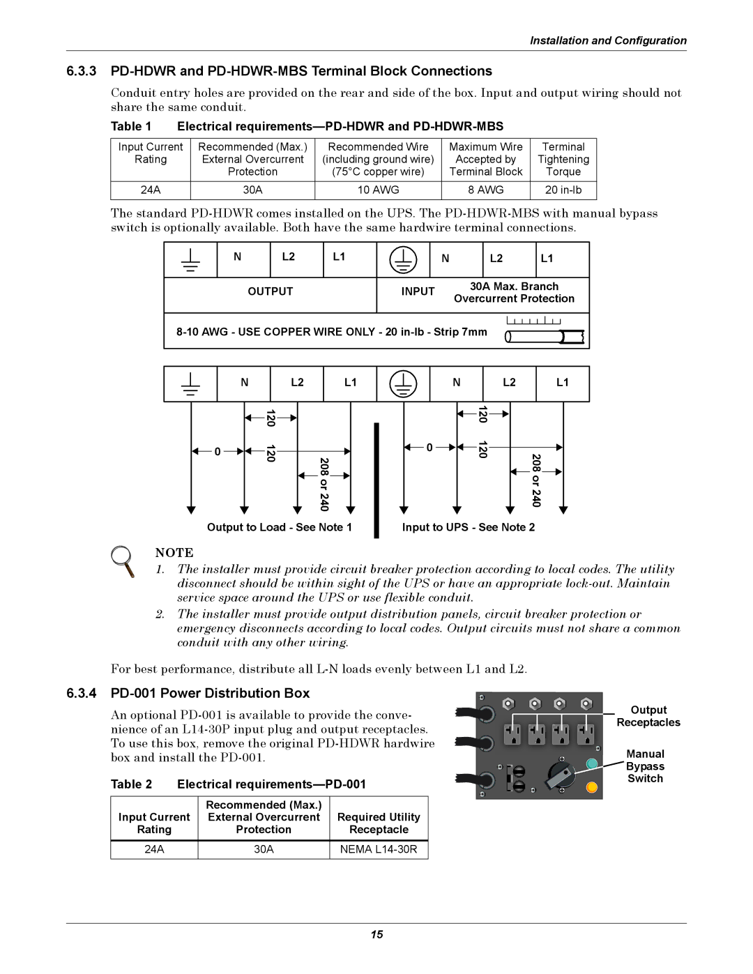
6.3.4 PD-001 Power Distribution Box
An optional
Table 2 | Electrical | ||
|
|
|
|
|
| Recommended (Max.) |
|
Input Current | External Overcurrent | Required Utility | |
Rating |
| Protection | Receptacle |
24A |
| 30A | NEMA |
|
|
|
|
Output
Receptacles
Manual
Bypass
Switch
15