Installation and Configuration
6.3Connect Input/Output Power
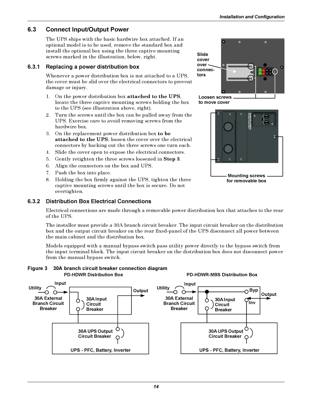
The UPS ships with the basic hardwire box attached. If an optional model is to be used, remove the standard box and install the optional box using the three captive mounting screws marked in the illustration, below, right.
6.3.1Replacing a power distribution box
Whenever a power distribution box is not attached to a UPS, the cover must be slid over the electrical connectors to prevent damage or injury.
1.On the power distribution box attached to the UPS, locate the three captive mounting screws holding the box to the UPS (see illustration above, right).
2.Turn the screws until the box can be pulled away from the UPS. Exercise care to avoid removing screws from the hardwire box.
3.On the replacement power distribution box to be attached to the UPS, loosen the cover over the electrical connectors by backing out the three screws one turn each.
4.Slide the cover open to expose the electrical connectors.
5.Gently retighten the three screws loosened in Step 3.
6.Align the connectors on the box and UPS.
7.Push the box into place.
8.Holding the box firmly against the UPS, tighten the three captive mounting screws until the box is secure. Do not overtighten.
Slide cover over connec- tors
Loosen screws to move cover
THEMANUAL | DISCONNECT |
BYPASS SWITCH. | BYPASS POWER TO |
Mounting screws for removable box
6.3.2Distribution Box Electrical Connections
Electrical connections are made through a removable power distribution box that attaches to the rear of the UPS.
The installer must provide a 30A branch circuit breaker. The input circuit breaker on the distribution box and the output circuit breaker on the rear
Models equipped with a manual bypass switch pass utility power directly to the bypass switch from the input terminal block. The input circuit breaker on the distribution box does not disconnect power from the manual bypass switch.
Figure 3 30A branch circuit breaker connection diagram
Input |
| Input |
|
| |
Utility | Output | Utility |
| Byp | |
30A External | 30A Input | 30A External | 30A Input | Output | |
Inv | |||||
Branch Circuit | Circuit | Branch Circuit | Circuit | ||
Breaker | Breaker | Breaker | Breaker |
|
30A UPS Output | 30A UPS Output |
Circuit Breaker | Circuit Breaker |
UPS - PFC, Battery, Inverter | UPS - PFC, Battery, Inverter |
14