Communications
11.0COMMUNICATIONS
11.1Communications Interface Port
The UPStation
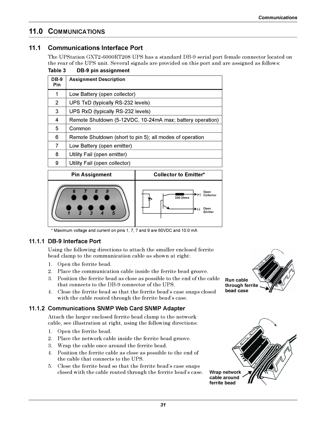
Table 3 DB-9 pin assignment
Pin
1Low Battery (open collector)
2UPS TxD (typically
3 UPS RxD (typically
4 Remote Shutdown
5Common
6Remote Shutdown (short to pin 5); all modes of operation
7 Low Battery (open emitter)
8 Utility Fail (open emitter)
9 Utility Fail (open collector)
| Pin Assignment | Collector to Emitter* | ||||
| 6 | 7 | 8 | 9 | (+) | Open |
|
|
|
|
| Collector | |
|
|
|
|
| 330 Ohms |
|
|
|
|
|
| Open | |
1 | 2 |
| 3 | 4 | 5 | Emitter |
|
| |||||
* Maximum voltage and current on pins 1, 7, 7 and 9 are 60VDC and 10.0 mA
11.1.1DB-9 Interface Port
Using the following directions to attach the smaller enclosed ferrite bead clamp to the communication cable as shown at right:
1.Open the ferrite bead.
2.Place the communication cable inside the ferrite bead groove.
3.Position the ferrite bead as close as possible to the end of the cable that connects to the
4.Close the ferrite bead so that the ferrite bead’s case snaps closed with the cable routed through the ferrite bead’s case.
Run cable through ferrite ![]() bead case
bead case
11.1.2Communications SNMP Web Card SNMP Adapter
Attach the larger enclosed ferrite bead clamp to the network cable, see illustration at right, using the following directions:
1.Open the ferrite bead.
2.Place the network cable inside the ferrite bead groove.
3.Wrap the cable once around the ferrite bead.
4.Position the ferrite cable as close as possible to the end of the cable that connects to the UPS.
5.Close the ferrite bead so that the ferrite bead’s case snaps
closed with the cable routed through the ferrite bead’s case. Wrap network
cable around ![]() ferrite bead
ferrite bead
31