Installation and Configuration
6.4Install the Grounding Electrode Conductor
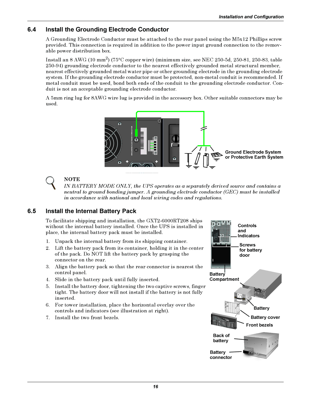
A Grounding Electrode Conductor must be attached to the rear panel using the M5x12 Phillips screw provided. This connection is required in addition to the power input ground connection to the remov- able power distribution box.
Install an 8 AWG (10 mm2) (75°C copper wire) (minimum size, see NEC
A 5mm ring lug for 8AWG wire lug is provided in the accessory box. Other suitable connectors may be used.
| GROUNDING ELECTRODE CONDUCTOR |
+ | + |
Ground Electrode System or Protective Earth System
NOTE
IN BATTERY MODE ONLY, the UPS operates as a separately derived source and contains a neutral to ground bonding jumper. A grounding electrode conductor (GEC) must be installed in accordance with national and local wiring codes and regulations.
6.5Install the Internal Battery Pack
To facilitate shipping and installation, the
1.Unpack the internal battery from its shipping container.
2.Lift the battery pack from its container, holding it in the center of the pack. Do NOT lift the battery pack by grasping the connector on the rear.
3.Align the battery pack so that the rear connector is nearest the control panel.
4.Slide in the battery pack until fully inserted.
5.Install the battery door, tightening the two captive screws, finger tight. The battery door will not install if the battery is not fully inserted.
6.For tower installation, place the horizontal overlay over the controls and indicators (see illustration at right).
7.Install the two front bezels.
Controls and Indicators
Screws for battery door
Battery
Compartment
Battery
![]() Battery cover
Battery cover
Front bezels
Back of battery
Battery ![]()
![]()
![]() connector
connector
16