Piping
2.3Liebert XDP Interconnection with Liebert XD Cooling Modules
All piping must be ASTM (American Society for Testing and Materials) Type L copper pipe.
The Liebert XDP may be connected to Liebert XD cooling modules with either Liebert’s XD prefabri- cated piping assembly or with rigid,
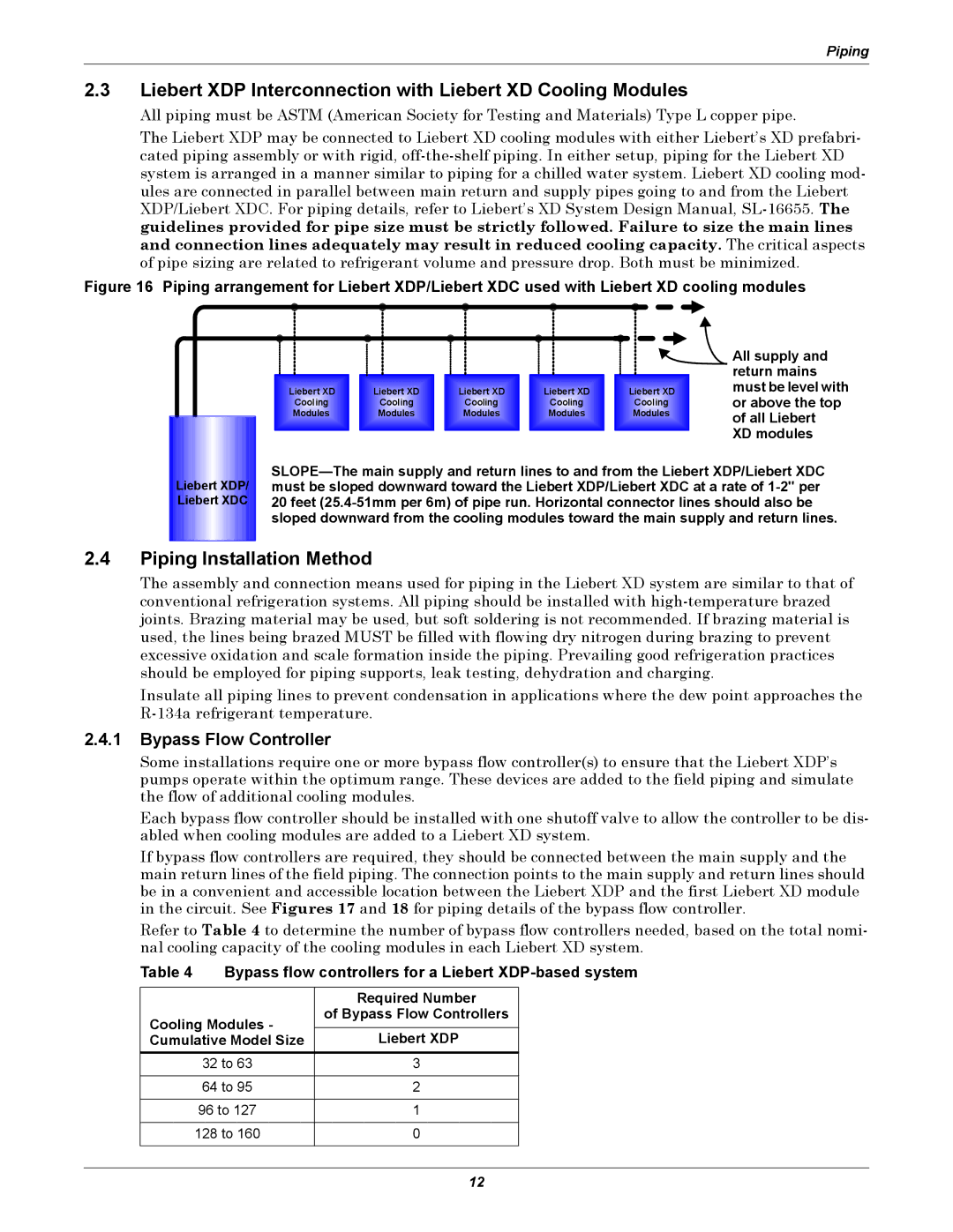
Figure 16 Piping arrangement for Liebert XDP/Liebert XDC used with Liebert XD cooling modules
Liebert XDP/ Liebert XDC
|
|
|
|
| All supply and |
|
|
|
|
| return mains |
Liebert XD | Liebert XD | Liebert XD | Liebert XD | Liebert XD | must be level with |
Cooling | Cooling | Cooling | Cooling | Cooling | or above the top |
Modules | Modules | Modules | Modules | Modules | of all Liebert |
|
|
|
|
| |
|
|
|
|
| XD modules |
2.4Piping Installation Method
The assembly and connection means used for piping in the Liebert XD system are similar to that of conventional refrigeration systems. All piping should be installed with
Insulate all piping lines to prevent condensation in applications where the dew point approaches the
2.4.1Bypass Flow Controller
Some installations require one or more bypass flow controller(s) to ensure that the Liebert XDP’s pumps operate within the optimum range. These devices are added to the field piping and simulate the flow of additional cooling modules.
Each bypass flow controller should be installed with one shutoff valve to allow the controller to be dis- abled when cooling modules are added to a Liebert XD system.
If bypass flow controllers are required, they should be connected between the main supply and the main return lines of the field piping. The connection points to the main supply and return lines should be in a convenient and accessible location between the Liebert XDP and the first Liebert XD module in the circuit. See Figures 17 and 18 for piping details of the bypass flow controller.
Refer to Table 4 to determine the number of bypass flow controllers needed, based on the total nomi- nal cooling capacity of the cooling modules in each Liebert XD system.
Table 4 Bypass flow controllers for a Liebert XDP-based system
| Required Number |
Cooling Modules - | of Bypass Flow Controllers |
| |
Cumulative Model Size | Liebert XDP |
32 to 63 | 3 |
|
|
64 to 95 | 2 |
|
|
96 to 127 | 1 |
|
|
128 to 160 | 0 |
|
|
12