Product Description
2.Determine which knockouts in the electrical enclosure will be used and remove them (see Figure 11).
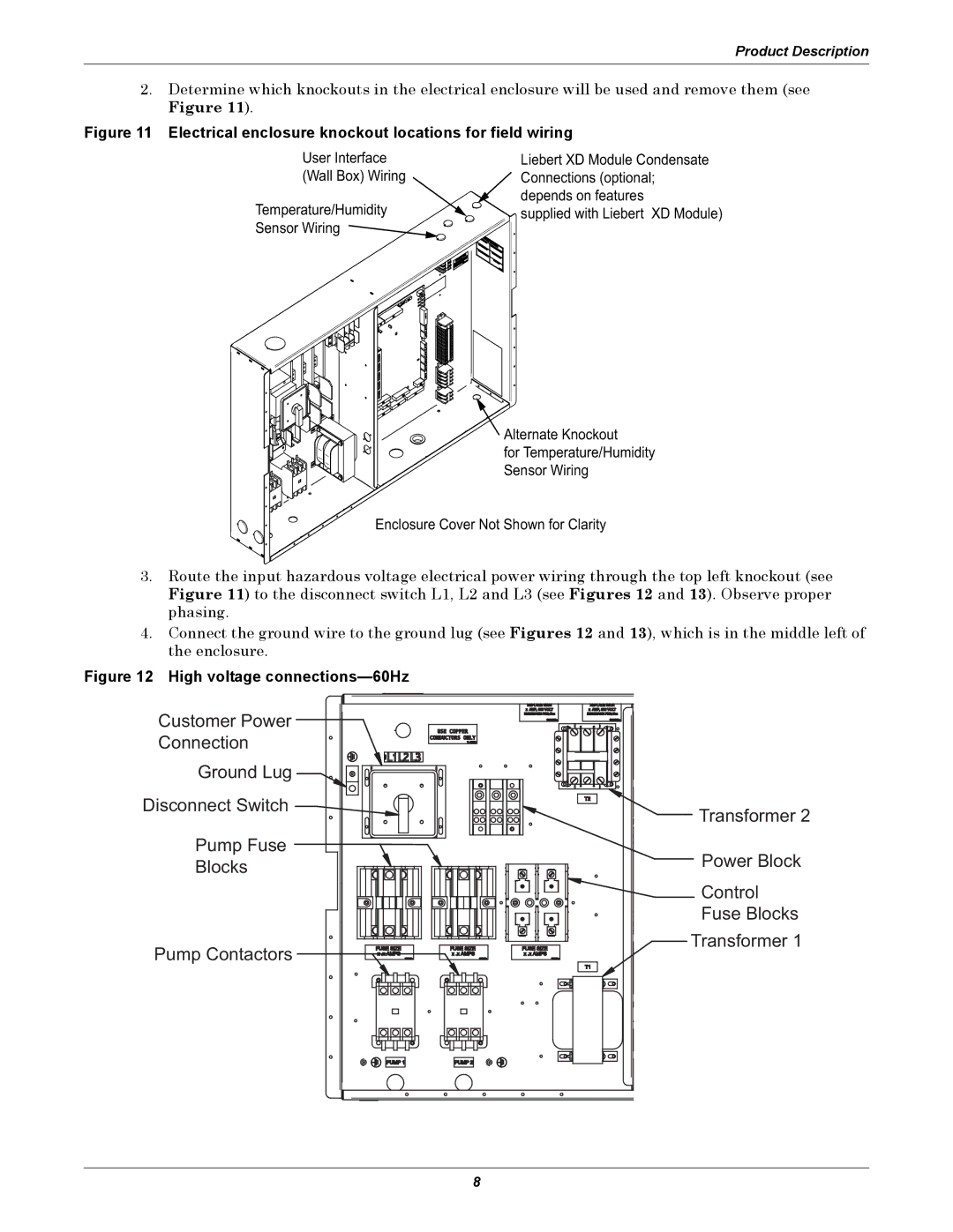
Figure 11 Electrical enclosure knockout locations for field wiring
User Interface
(Wall Box) Wiring
Temperature/Humidity Sensor Wiring ![]()
Liebert XD Module Condensate Connections (optional; depends on features
![]()
![]() supplied with Liebert XD Module)
supplied with Liebert XD Module)
![]() Alternate Knockout
Alternate Knockout
for Temperature/Humidity
Sensor Wiring
Enclosure Cover Not Shown for Clarity
3.Route the input hazardous voltage electrical power wiring through the top left knockout (see Figure 11) to the disconnect switch L1, L2 and L3 (see Figures 12 and 13). Observe proper phasing.
4.Connect the ground wire to the ground lug (see Figures 12 and 13), which is in the middle left of the enclosure.
Figure 12 High voltage connections—60Hz
Customer Power |
| |
Connection |
| |
Ground Lug |
| |
Disconnect Switch | Transformer 2 | |
| ||
Pump Fuse | Power Block | |
Blocks | ||
| ||
| Control | |
| Fuse Blocks | |
Pump Contactors | Transformer 1 | |
| ||
| 8 |