Piping
2.5Piping Details—Shut-Off/Isolation Valves
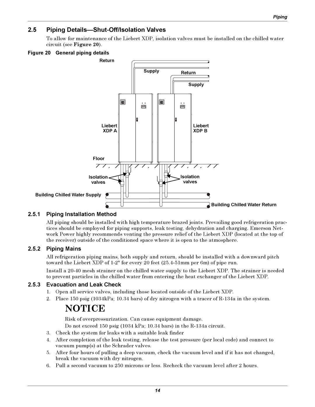
To allow for maintenance of the Liebert XDP, isolation valves must be installed on the chilled water circuit (see Figure 20).
Figure 20 General piping details
Return
Supply Return
Supply
Liebert
XDP A
Liebert
XDP B
Floor |
|
Isolation | Isolation |
valves | valves |
Building Chilled Water Supply
![]()
![]()
![]()
![]() Building Chilled Water Return
Building Chilled Water Return
2.5.1Piping Installation Method
All piping should be installed with high temperature brazed joints. Prevailing good refrigeration prac- tices should be employed for piping supports, leak testing, dehydration and charging. Emerson Net- work Power highly recommends venting the pressure relief of the Liebert XDP (located at the top of the receiver) outside of the conditioned space where it is open to the atmosphere.
2.5.2Piping Mains
All refrigeration piping mains, both supply and return, should be installed with a downward pitch toward the Liebert XDP of
Install a
2.5.3Evacuation and Leak Check
1.Open all service valves, including those located outside of the Liebert XDP.
2.Place 150 psig (1034kPa; 10.34 bars) of dry nitrogen with a tracer of
NOTICE
Risk of overpressurization. Can cause equipment damage.
Do not exceed 150 psig (1034 kPa; 10.34 bars) in the
3.Check the system for leaks with a suitable leak finder
4.After completion of the leak testing, release the test pressure (per local code) and connect to vacuum pump(s) at the Schrader valves.
5.After four hours of pulling a deep vacuum, check the vacuum level and if it has not changed, break the vacuum with dry nitrogen.
6.Pull a second vacuum to 250 microns or less. Recheck the vacuum level after 2 hours.
14