Checklist for Liebert XDP Startup
If there is no “Loss of Flow” alarm
This should prompt an alarm for “loss of flow on P1.” This alarm confirms that the switch has opened on low pressure (below 6 psi; 41kPa; 0.41 bars).
If there is a “Loss of Flow” alarm
However, if there is flow, but the differential reading is faulty, the level will slowly drop, indicating flow, while the loss of flow alarm is annunciated.
Check the pressure differential physically by making sure that the electrical connections are properly connected. Then check the pressure differential electrically by making sure that the unit has 24VAC across it.
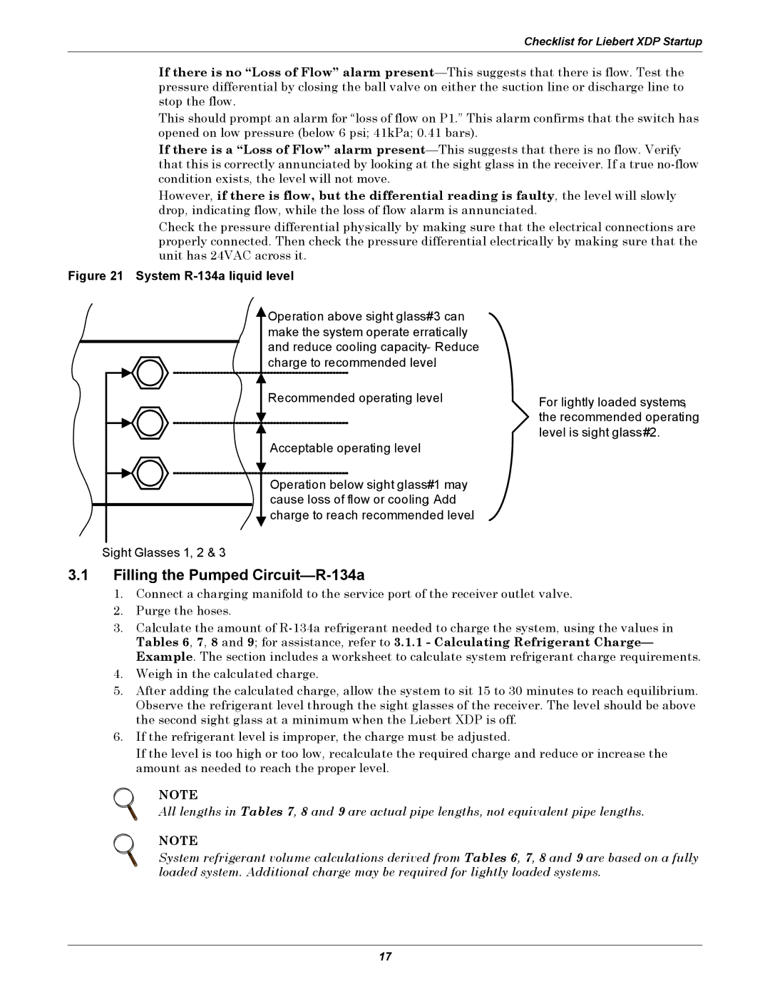
Figure 21 System R-134a liquid level
![]() Operation above sight glass#3 can make the system operate erratically and reduce cooling capacity- Reduce charge to recommended level.
Operation above sight glass#3 can make the system operate erratically and reduce cooling capacity- Reduce charge to recommended level.
Recommended operating level
Acceptable operating level
Operation below sight glass#1 may cause loss of flow or cooling. Add charge to reach recommended level.
For lightly loaded systems, the recommended operating level is sight glass#2.
Sight Glasses 1, 2 & 3
3.1Filling the Pumped Circuit—R-134a
1.Connect a charging manifold to the service port of the receiver outlet valve.
2.Purge the hoses.
3.Calculate the amount of
4.Weigh in the calculated charge.
5.After adding the calculated charge, allow the system to sit 15 to 30 minutes to reach equilibrium. Observe the refrigerant level through the sight glasses of the receiver. The level should be above the second sight glass at a minimum when the Liebert XDP is off.
6.If the refrigerant level is improper, the charge must be adjusted.
If the level is too high or too low, recalculate the required charge and reduce or increase the amount as needed to reach the proper level.
NOTE
All lengths in Tables 7, 8 and 9 are actual pipe lengths, not equivalent pipe lengths.
NOTE
System refrigerant volume calculations derived from Tables 6, 7, 8 and 9 are based on a fully loaded system. Additional charge may be required for lightly loaded systems.
17