A-5

INSTALLATION

A-5

Return to Section TOC

Return to Section TOC

Return to Section TOC

Return to Section TOC

Return to Master TOC

Return to Master TOC

Return to Master TOC

Return to Master TOC

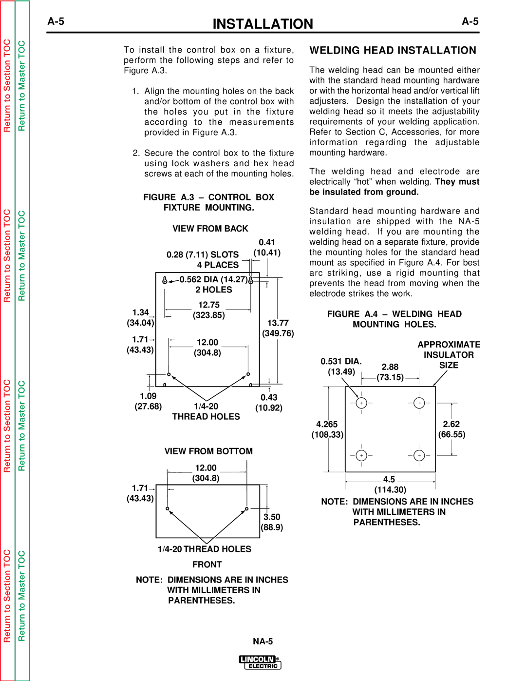
To install the control box on a fixture, perform the following steps and refer to Figure A.3.

1.Align the mounting holes on the back and/or bottom of the control box with the holes you put in the fixture according to the measurements provided in Figure A.3.

2.Secure the control box to the fixture using lock washers and hex head screws at each of the mounting holes.

FIGURE A.3 – CONTROL BOX

FIXTURE MOUNTING.


VIEW FROM BACK


0.41


0.28 (7.11) SLOTS

(10.41)


4 PLACES


0.562 DIA (14.27)


2 HOLES


1.34


12.75


(323.85)


(34.04)


13.77

1.71


12.00


(349.76)


(43.43)


(304.8)


1.09


0.43

(27.68)

1/4-20

(10.92)


THREAD HOLES


VIEW FROM BOTTOM

12.00

(304.8)

1.71

(43.43)

3.50

(88.9)

1/4-20 THREAD HOLES

FRONT

NOTE: DIMENSIONS ARE IN INCHES

WITH MILLIMETERS IN PARENTHESES.

WELDING HEAD INSTALLATION

The welding head can be mounted either with the standard head mounting hardware or with the horizontal head and/or vertical lift adjusters. Design the installation of your welding head so it meets the adjustability requirements of your welding application. Refer to Section C, Accessories, for more information regarding the adjustable mounting hardware.

The welding head and electrode are electrically “hot” when welding. They must be insulated from ground.

Standard head mounting hardware and insulation are shipped with the NA-5 welding head. If you are mounting the welding head on a separate fixture, provide the mounting holes for the standard head mount as specified in Figure A.4. For best arc striking, use a rigid mounting that prevents the head from moving when the electrode strikes the work.

FIGURE A.4 – WELDING HEAD

MOUNTING HOLES.

APPROXIMATE

INSULATOR

0.531 DIA. 2.88SIZE

(13.49)

(73.15)


4.265


2.62￿

(108.33)


(66.55)


4.5

(114.30)

NOTE: DIMENSIONS ARE IN INCHES

WITH MILLIMETERS IN PARENTHESES.

NA-5

Page 12
Image 12
Lincoln Electric NA-5NF, NA-5SF service manual Welding Head Installation, Places, Thread Holes View from Bottom

NA-5S, NA-5N, NA-5SF, NA-5NF specifications

The Lincoln Electric NA-5NF, NA-5SF, NA-5N, and NA-5S are advanced welding helmets that are pivotal in enhancing the safety and efficiency of welders in various applications. These models are designed to provide exceptional protection and visibility, making them indispensable tools in the welding industry.

One of the main features of the NA-5 series is the auto-darkening filter technology. This feature allows the helmet to automatically adjust its shade based on the intensity of the arc. As the welder strikes an arc, the lens darkens instantaneously, shielding the eyes from harmful rays generated during the welding process. This functionality not only ensures safety but also enhances productivity, as welders do not need to manually flip the helmet up and down.

The helmets are equipped with a wide viewing area that allows for better visibility and precision while working. With a large lens, welders can easily monitor their work and surrounding environment, minimizing the risk of accidents. Additionally, the lightweight design of the NA-5NF, NA-5SF, NA-5N, and NA-5S provides comfort during extended periods of use, reducing neck strain and fatigue.

The NA-5 series is also well-regarded for its durability. Constructed from impact-resistant materials, these helmets can withstand the rigors of demanding work environments. This durability extends the lifespan of the helmet, making it a cost-effective investment for both professional and hobbyist welders.

Another notable characteristic is the adjustable sensitivity and delay settings found in certain models. These settings allow the user to customize the helmet based on their specific welding conditions. For instance, a welder can increase sensitivity for low-amperage tasks or adjust the delay to allow for a smoother transition from dark to light after completing a weld.

Furthermore, the helmets come with a reliable battery life, ensuring that they can be used for long periods without interruption. Some models also feature solar assist functionality, which helps recharge the auto-darkening filter, enhancing their overall efficiency.

In summary, the Lincoln Electric NA-5NF, NA-5SF, NA-5N, and NA-5S welding helmets represent a significant advancement in personal protective equipment for welders. Their combination of auto-darkening technology, wide viewing area, lightweight design, durability, and customizable settings makes them an excellent choice for anyone engaged in welding tasks. With these helmets, users can achieve greater safety and efficiency in their work, enabling them to focus on their craft with peace of mind.