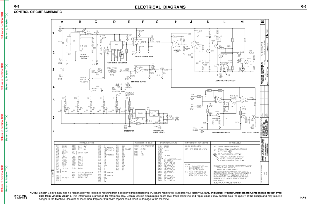
Lincoln Electric NA-5NF, NA-5SF service manual Control Circuit Schematic, C D E F G H L M

Models: NA-5S NA-5N NA-5SF NA-5NF

1 152
Download 152 pages 30.16 Kb
Page 148
Image 148

TOC

G-8

ELECTRICAL DIAGRAMS

CONTROL CIRCUIT SCHEMATIC


G-8

Section

Master

A B C D E F G H

J K L M

B

Return to

Return to Section TOC

Return to Section TOC

Return to Section TOC

Return to

Return to Master TOC

Return to Master TOC

Return to Master TOC

1

525

A5H


11 12 10

Q207

520


+10.00V


6

2

R243

525


R201

3

R204

A5H

C204 +

X201

R209


C217


C221


512

R221


9

8


-

4

X203

B4E

C208

2

B4J


10


A


3


1 R211

R217

6 -


C219

R239


R230


C209


D206

CW

R229

LO

R238


-

4 X204


C224

R233


2


R235


6682-2

SHT. NO. L

81

2

3

510

A5H

C214 +

500

A6H

5

4

C202

R203


+


C203

R206

R207


7


R205


13


C201

+10.00 V


REFERENCE


SUPPLY


510P


525


525A


A5H


L201


TO TACH


555


PICK-UP


P.C. BOARD


11

X202


+

11


D

1


5


5

+

7


C218

C212

X203


12 2 3


4

R210


CONTROL

C216

CW

500


AMP


C205

R208

CAL

A6H


C206 +


ACTUAL SPEED BUFFER


TACH SIGNAL CONVERTER


511


FROM OPTION


-

X203

B4E

511A


13

511 B5J


SPEED


AND

632

B


SETTING

12

14

R242

R218


PROCEDURE


+


PC BOARD


+


C213

C228


E2D


C215


N.A.


510P


B3C

SET SPEED BUFFER


A


3

+

1

+


Q204

C229


11


R222

CW


R226


HI


C210


R231


Q203


C220


QU201


C225


D208


C223


540

A1H


D205


C211


R227

R228

R232

C119


R234


PT


101A


500


N.B


A6H


ARMATURE FIRING CIRCUIT

DZ203

628


D8A


Q205

Q206

R236

DZ202

C227

R237


NA-5SCHEMATIC CONTROLCIRCUIT

10-4-

SUP'S'D'G

EQUIP. TYPE

SUBJECT SCALE NONE

REF.

LINCOLN ELECTRIC CO. CLEVELAND, OHIO U.S.A.

DADDATE 7-2-92 CHK

4

L202

510A

511512

B3GB1G

SETACTUAL

S7A

SPEED

SET-ACTUAL

R212

R214

THE

DR

5

6

142T


95S


142


95

R414


R412


R409


R407

CW

CAL

CW

CAL


CW

CAL


CW

R413

R411


R408


R406


C407


C406

C409


C408


CAL

C405

57

R405

CW

R404


SPEEDMETER


519

CALIBRATION


JUMPER


57F


R402


CAL

CW

CAL


R401


C404

4


DM401


TP4


R403

C403

E

C


R410


510P


B3C


TP5

1 +5V


2

X401


OUT

IN


GND


D401


+


+


C402


C401

D403


D404


510


C7E


D402

601A6E

602A6E

512


FAST-SLOW


R240


-


-


8


ACCELER


8 D204

B1G


9


9

B


10

C


JUMPER

10


+

X203

R219

PIN


+

X204


525


PIN


R225


511


F

S


R241

A5H


525


CW


B3G


A5H


R220


Q201


ACC


R223


D202


DZ201


R213


+


C207


Q202


R224

C222


R215

C226

R216


D203


D201


500

FEED

586


A6H


No.


SPECIFIED TOLERANCECh'ge. Sht.

9-11-90D

19-7-91J

15-5-92N

10-7-92A

PER E2056

DECIMALS IS .02 DECIMALS IS .002 IS .5 OF A DEGREE 92B3-6-

TOLERANCE t(" ") TO AGREE

PUBLISHED STANDARDS.

7


SPEEDMETER


SPEEDMETER


POWER SUPPLY


CONTROL P.C. BOARD


TACHOMETER P.C. BOARD

SPEEDMETER P.C. BOARD


C201

.022/25

DZ201

6.8 V., 1 2/ W.

R201

1K

R227

6.8K

OCI301

OPTO-INTERRUPTER

C401

500/50


C202

.022/25

DZ202

16.0 V., 1 W.

R203

500 TRIMMER

R228

10K


C402

4.7/35


C203

18/15

DZ203

3.0 V., 1 W.

R204

1.00K, 1/4W, 1%

R229

20K TRIMMER

Q301

2N4123

C403

.022/25


C204

4.7/35


R205

2.94K, 1.4W, 1%

R230

27K


THRU


C205

.0033/200

L201

330 uH, 110mA

R206

15K

R231

15

R301

1K

C409


C206

.47/50

L202

R207

10K

R232

100

R302

15K

D401


C207

18/15


R208

100K TRIMMER

R233

6.8K

R304

1.3K

D402

1A, 400V


C208

4/50

Q201

2N4123

R209

33K

R234

2.7K


D403


C209

.047/100

Q202

2N4123

R210

10K

R235

10K


D404

+5V VOLTAGE REGULATOR


C210

4.7/35

Q203

2N4123

R211

270

R236

15K


X401


C211

.15/200

Q204

2N4125

R212

15K

R237

10K


R401

2K TRIMMER


C212

.022/25

Q205

BS170

R213

47K

R238

1M


R402

17.8K, 1/4W, 1%


C213

.022/25

Q206

2N4123

R214

15K

R239

15K


R403

2.80K, 1/4W, 1%


C214

4.7/35

Q207

2N5816

R215

100K

R240

5.6K


R404

2K TRIMMER


C215

18/15


R216

1K

R241

15K


R405

18.2K, 1/4W, 1%


C216

100pf/100

QU201

2N6027

R217

1K

R242

270


R406

5K TRIMMER

L

C217


R218

1K

R243

10


R407

33.2K, 1/4W, 1%

THRU

.022/25


R219

33K


R408

5K TRIMMER

6682-


VOLTAGE REGULATOR


C229


X201

R220

50K TRIMMER


R409

52.3K 1/4W, 1%


X202

F- TO -V CONVERTER

R221

15K


R410

10

D201


X203

QUAD OP-AMP

R222

10K TRIMMER


R411

5K TRIMMER

2

THRU

1A, 400 V

X204

QUAD OP-AMP

R223

33K


R412

31.6K, 1/4W, 1%


D206


R224

100K


R413

5K TRIMMER


D208


R225

1K


R414

51.1K, 1/4W, 1%


R226

10K


ENABLE


D7J

ACCELERATION CIRCUIT

FEED ENABLE CIRCUIT


COMPONENTS NOT ON P.C. BOARD


KEY TO SYMBOLS


DM401 DIGITAL METER


POWER SUPPLY SOURCE POINT


S7A

SPDT SPEED SET-ACTUAL


COMMON CONNECTION TO ANALOG POWER


SUPPLY; 510 A5H


SCHEMATIC LOCATION REFERENCE


HORIZONTAL CO-ORDINATE LETTER


VERTICAL CO-ORDINATE NUMBER


SCHEMATIC IDENTIFICATION LETTER


NOTES:


UNLESS OTHERWISE SPECIFIED, COMPONENT VALUES OF:

N.A.

511 IS CONNECTED TO 511A


BY CONNECTION TO


CAPACITORS = MFD/VOLTS


VOLTAGE P.C. BOARD.


RESISTORS = OHMS, 1 2 /WATT


N.B. THESE COMPONENTS ARE


SINCE COMPONENTS OR CIRCUITRY ON A PRINTED


CIRCUIT BOARD MAY CHANGE WITHOUT AFFECTING THE


LOCATED ON POWER P.C.


INTERCHANGEABILITY OF A COMPLETE BOARD, THIS


BOARD (SEE SCHEMATIC A).


DIAGRAM MAY NOT SHOW THE EXACT COMPONENTS


OR CIRCUITRY OF CONTROLS HAVING A COMMON


CODE NUMBER.


ELECTRICAL SYMBOLS PER E1537.

UNLESS OTHERWISE

ON HOLE SIZES ON 2 PLACE ON 3 PLACE

ON ALL ANGLES

MATERIAL WITH


THIS SHEET CONTAINS PROPRIETARYINFORMATION

OWNED BY THE LINCOLN ELECTRIC CO. AND IS

NOT TO BE REPRODUCED, DISCLOSED OR USED

WITHOUT THE EXPRESS PERMISSION OF

THE LINCOLN ELECTRIC CO.


CONTROL CODES

9147

9338

FOR NA-5


NOTE: Lincoln Electric assumes no responsibility for liablilities resulting from board level troubleshooting. PC Board repairs will invalidate your factory warranty. Individual Printed Circuit Board Components are not avail- able from Lincoln Electric. This information is provided for reference only. Lincoln Electric discourages board level troubleshooting and repair since it may compromise the quality of the design and may result in danger to the Machine Operator or Technician. Improper PC board repairs could result in damage to the machine.

NA-5

Page 148
Image 148
Lincoln Electric NA-5NF, NA-5SF service manual Control Circuit Schematic, C D E F G H L M

NA-5S, NA-5N, NA-5SF, NA-5NF specifications

The Lincoln Electric NA-5NF, NA-5SF, NA-5N, and NA-5S are advanced welding helmets that are pivotal in enhancing the safety and efficiency of welders in various applications. These models are designed to provide exceptional protection and visibility, making them indispensable tools in the welding industry.

One of the main features of the NA-5 series is the auto-darkening filter technology. This feature allows the helmet to automatically adjust its shade based on the intensity of the arc. As the welder strikes an arc, the lens darkens instantaneously, shielding the eyes from harmful rays generated during the welding process. This functionality not only ensures safety but also enhances productivity, as welders do not need to manually flip the helmet up and down.

The helmets are equipped with a wide viewing area that allows for better visibility and precision while working. With a large lens, welders can easily monitor their work and surrounding environment, minimizing the risk of accidents. Additionally, the lightweight design of the NA-5NF, NA-5SF, NA-5N, and NA-5S provides comfort during extended periods of use, reducing neck strain and fatigue.

The NA-5 series is also well-regarded for its durability. Constructed from impact-resistant materials, these helmets can withstand the rigors of demanding work environments. This durability extends the lifespan of the helmet, making it a cost-effective investment for both professional and hobbyist welders.

Another notable characteristic is the adjustable sensitivity and delay settings found in certain models. These settings allow the user to customize the helmet based on their specific welding conditions. For instance, a welder can increase sensitivity for low-amperage tasks or adjust the delay to allow for a smoother transition from dark to light after completing a weld.

Furthermore, the helmets come with a reliable battery life, ensuring that they can be used for long periods without interruption. Some models also feature solar assist functionality, which helps recharge the auto-darkening filter, enhancing their overall efficiency.

In summary, the Lincoln Electric NA-5NF, NA-5SF, NA-5N, and NA-5S welding helmets represent a significant advancement in personal protective equipment for welders. Their combination of auto-darkening technology, wide viewing area, lightweight design, durability, and customizable settings makes them an excellent choice for anyone engaged in welding tasks. With these helmets, users can achieve greater safety and efficiency in their work, enabling them to focus on their craft with peace of mind.