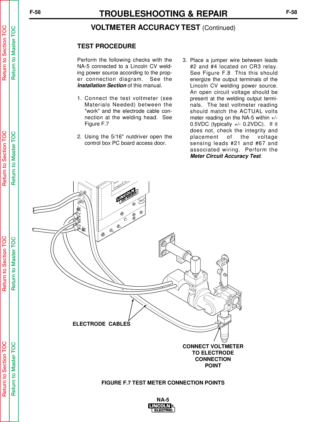
NA-5S, NA-5N, NA-5SF, NA-5NF specifications
The Lincoln Electric NA-5NF, NA-5SF, NA-5N, and NA-5S are advanced welding helmets that are pivotal in enhancing the safety and efficiency of welders in various applications. These models are designed to provide exceptional protection and visibility, making them indispensable tools in the welding industry.One of the main features of the NA-5 series is the auto-darkening filter technology. This feature allows the helmet to automatically adjust its shade based on the intensity of the arc. As the welder strikes an arc, the lens darkens instantaneously, shielding the eyes from harmful rays generated during the welding process. This functionality not only ensures safety but also enhances productivity, as welders do not need to manually flip the helmet up and down.
The helmets are equipped with a wide viewing area that allows for better visibility and precision while working. With a large lens, welders can easily monitor their work and surrounding environment, minimizing the risk of accidents. Additionally, the lightweight design of the NA-5NF, NA-5SF, NA-5N, and NA-5S provides comfort during extended periods of use, reducing neck strain and fatigue.
The NA-5 series is also well-regarded for its durability. Constructed from impact-resistant materials, these helmets can withstand the rigors of demanding work environments. This durability extends the lifespan of the helmet, making it a cost-effective investment for both professional and hobbyist welders.
Another notable characteristic is the adjustable sensitivity and delay settings found in certain models. These settings allow the user to customize the helmet based on their specific welding conditions. For instance, a welder can increase sensitivity for low-amperage tasks or adjust the delay to allow for a smoother transition from dark to light after completing a weld.
Furthermore, the helmets come with a reliable battery life, ensuring that they can be used for long periods without interruption. Some models also feature solar assist functionality, which helps recharge the auto-darkening filter, enhancing their overall efficiency.
In summary, the Lincoln Electric NA-5NF, NA-5SF, NA-5N, and NA-5S welding helmets represent a significant advancement in personal protective equipment for welders. Their combination of auto-darkening technology, wide viewing area, lightweight design, durability, and customizable settings makes them an excellent choice for anyone engaged in welding tasks. With these helmets, users can achieve greater safety and efficiency in their work, enabling them to focus on their craft with peace of mind.

