G-3 | | | | | | | | | | | | | | | | | | | | | | | | | | | | | | | | | ELECTRICAL DIAGRAMS | | | | | | | | | | | | | | | | | | | | | | | G-3 |
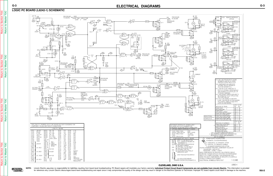
LOGIC PC BOARD (L6242-1) SCHEMATIC | | | | | | | | | | | | | | | | | | | | | | | | | | | | | | | | | | | | | | | | | | | | | | | | | | | | | | | | | | |
| LED 7B | | | | | | | | | | | | PROCEDURE | | 583S | | | | | | | | | | | | | | | | | | | | | | | | | | | | | | | | 564 | PROCEDURE | | | | | 610 | | | | D1021 D1023 | REMOTE INTERFACE | |
| | | | | | | | | | | | | | PC BOARD | | START TIME | WELD TIME | | | | | | | | | | | | | | | | | | | | | | | | | | | | | | | | | | A6G | | | | |
| 515 | | | | | | | | | | | | | | | | | | | | | | | | | | | | | | | | | | | | | | | | | | | | | | | | PC BOARD | | | | | | | | | | | | | | | OPTION | | |
| | | | | | | | | | | | | | | | | | | | OVER | | | | | | | | | | | | | | | | | | | | | | | | | | | | | | | | | | | | | | | | | | | | | | |
| | | | | | | | | | | | | | | | | | | OVER | | | X705 | P10 | | 9 | X701 | | | | | | | | | B | X705 | | | | | R741 | | | | WELD | | | | | | | | | | | | 24 | RED | | | | | R1001 | |
| D8C | | 581A | | | 581 R706 | R707 | | | | | | 1 | X707 | | | | | | | | | | | | | | | | | 8 | | | | | | R742 | C727 | | PROCEDURE | | | | | | | | | R722 | A7E | VAC | D1022 | | | 1001 | |
| | | | | | | | | | | | | | | F | P5 | | | | | C | N.C. | | | | | | | 9 | | | | | | | | | ENABLE | | | | | | D718 | | TRAVEL | | | | | | | |
| | D712 | START | | | | | | | | | | | | | | | | 3 | 4 | | | | 10 | 8 | | | | | | | | | | | | | | | Q711 | | | | | | | | | | | D1024 | | D1001 | | | | |
| | DISABLE | | | | | | | | | | | | | | | | | | | | | 694 | | | | | | | | | | | | | | | | | | | | | | | | | | | | | | CR2 | | LED 7H | | RED | | | CR | | D1002 | |
| | | | | | | | | | | | | | | | | | | | | | | | | | | | | | | | | | | | | | | | | | | | | | | | | | | | | | | | | | | | | | | | | | | | | |
| | | | | S801A | | | | | | DZ702 | | 2 | A | | 3 | | | | | | 692 | | | | | X705 | | | | | | | | | | | | | | | | | | 500 | | | | | | | | | | | D722 | | | | F1001 | D1003 + | | D1004 | |
| | | | | | | N.A. | | C706 | | | | | | | | | | | | | | | | | | | | | | | | | | | | | | | | | | | | | | | | | | | | | | | CR | C1001 | | |
| | | | | | | | | | | | | | | | | | | | | | | X701 | | | | | | | | | | | | | | | | | | | D9C | | | | | | | | | | | 589 | | | | | |
| | S5 | | | | | | | | | | | | | | | | | | | | | | | | | | | | | | | | | | | | | | | | | R720 | | | | | | | | | | | |
| | | | | | | | | | | | | | | | | | | | | | | 13 | E | | | | | | | | | | | | | | | | | | | | | | | | | | | | | 581A | 1001 | | SWITCH | | | 24V SIG. | | |
| | START | | | | | | | | | | | | | | | | | | | | N.D. | 12 | | D | 11 | 11 | | 10 | | | | | | | | | | | | | | | | | | | | | | | | | | R721 | | | Q702 | | | | | | | | | | |
| | | | | | | | | | | | | | | | | | | | | | | | | | | | | | | | | | | | | | | | | | | 560 | PROCEDURE | | | | | | | | D1005 | | | | | |
| | | | | | | | | | | | | | | | | | | | | | | | | | | | | | | | | | | | X705 | | | | | | | | | | | | D1A | | | | START | | | |
| | | | | | | | | | | | | | | | | | | | | | | | | | | | | | | | | | | | | | | | | | | | | | | | | | | | | | | | | |
| | | | | | | | | PROCEDURE 565 | | D708 | | 4 | X707 | | | | | | | | | | | | | | | | | | X701 | | | | | | | | | | | | PC BOARD | | | C719 | | | | | | | | | | |
| | | | | | | 500 | | | | 6 | | | | | | | | | | | | | | | | 1 | | | | 689 | | | | | | PRESET | | | | | | | | | | | R1002 | |
| | | | | | | | | | | | | | | | | | | | | | | | | | | | | A | | | | | | | | | | | | | | | | | | | | | | | | | | |
| | | | | | | D9C | | PC BOARD | | | | | 5 | B | | | | | | | | | | | | | | | | | | 2 | A | | 3 13 | | 12 | | | | | | | | | MONITOR | | | | | | | 500 | | | | | | | | D1006 | | D1007 | |
| | | | | | | | | 515 WELD TIME | | | | | | | | | | | | | | | | | | | | | | | | | | N.B. | | | OHMS | | | | | | ENABLE | | | | | | | | | | | | CR | SWITCH | | CR | | |
| | | | | | | | | | + | | | | | | | | | | | | | | | | | | | | | | | | | | | | 470 | | | R738 | | | | | | | | | | A7H | 610 | | | | | | SIGNAL | |
| | | | | | | | | | | | OVER | | | | | | | | | | | | | | | | | | | | | | | | | | | | | | | | | Q709 | | | | | | | | | | 582 | | 1002 | COMMON | | 1002 | |
| | | | | | | | | | D8C | | | R705 | | | | | | | | | | | | | | | | | | | | | | | | | | | | | | | | | | | | | | | | | | | | | | | |
| | | | | | | | | | | | | | | | | | | | | | | | | | | | | | | | | | | | | | | | | | | | | | | | | | | | | | | | | | | | | | | | | | | | | COMMOM | |
| | | | | | | | | R702 | | | R704 | | | | C705 | | | | | | | | 691 | | | | | | | | | | | B | | 6 | | | | | | + | | | | | C725 | | D8C | | | | | | | | | A6G | | D3A | | | | | D1008 + | C1002 D1009 | | |
| | | | | | | | | | | | | | 500 | | | | | | | | | | | | | | | | | | | | | | | CR6 | | | | | 500 | | | | | | | | | | | | | | | | | | | | | |
| | | | | | | | | | | | | | | | | | | | | | | | | | | | | | | | | | 5 | X701 | | | | | | | | | | | | | | 515 | | | | | | | | | | | | | | SWITCH | | | 24V SIG. | | |
| | | | | | | | | | LED 7C | | | | | D9C | | | | | | N.D. | | | | | | | | | | | 4 | | | | | .047 | | | | | | | | D9C | | R737 | | | | ELECTRODE | | | | | | | | D1010 | | | | | |
| | | | | | | | | | | | C728 | | | | | | | | | | | | | | | | | | | | | | | | | | | | | | | | | | | R727 | 586 | | 1003 | | | | | | |
| | | | | | D710 | | | | | | | | | | | | | | | | | | | | | | | | | | | | | | | | MFD | | | | | | | | | | | | | | | LT1 | R | | | | | | D1011 | | | | |
| | | | | | | | | | | | | | | | | | | | | | | | | | | | | | | | | | | | | | | | | | | | D726 | | | | | | | | HOT | | | | | | | CR | | | | STOP | R1003 | |
| | | | | | | | | | | | | | | | | | | | | | | | | | | | | | | | | | | | | | | | | | | | | | | | | | | | | | | | | | | | | | | | | | | |
| | | 582 | R703 | | | | DZ701 | | | | | | | | | | | | | | | | | | | | | | | | | | | | | | 500 | | | | | | D725 | | | | | | | | | CR3 | | | | | | | | CR | | D1012 | |
| | | | | | | | | | | | | | | | | | | | | | | | | | | | | | | | | | | | | | | | D9C | | | | | | | | | | | | | | | | | | | | | | | | | | |
| | | | | | | | | | | | 500 | | | | | | | | | | | | | | | | | | | | | | | | | | | | | | | | | 530 | HOLD-LOW | | | | | | D720 | | | D7J | | | | | | 1003 | | | |
| | | | | | | | | | | | | | | | | | | | | | | | | | | | | | | | | | | | | | | | | | | | | | | | | | | | | | | | | | | | | | | | |
| | | | | | | | C704 | | | | | | | | | | | | | | | | | | P6 | | | P8 | | | | | | | | | | X705 | | 584C | | | | | | | | | | | | | | | LED 7K | | | | | | | | | | |
| | | | | | | | | | | | | | | | | | | | | | | | | | | | | | X702 | | | | | | PROCEDURE | | | | C4D | DISABLE | | | | | | | | D723 | | | | | D1013 + | C1003 D1014 | | |
| | S6 | | | | | | | | | D9C | | | | | | | | 13 | X707 | | | | | | | | | 10 | | | | | C | 6 | | R735 | | | | | | | | | POWER | | | | | | |
| | | | | | | | | | | | | | | 515 | | | | | | | | | | | | C | 8 | | | 5 | CRATER | PC BOARD | | R725 | | | | | | | 682 | | | | | | | |
| | STOP | | | | | | | | | | | | | | | | | 12 | D | 11 | | | | | | | | | 9 | | | | | | | | | | | R736 | | Q708 | | | | | | | Q704 | | SOURCE | | | | SWITCH | | | 24V SIG. | | |
| | | | | | | | | | | | | | | | | | D8C | | | | | | | R709+ | | | | | | | | | | | | | | | TIME | | | | | | | | | | | | R726 | | | OUTPUT | | | | | | | | | | |
| | | | | 515 | | | | | | | | | | | | | | R710 | | | | | | | | | | | | | | | | | | | | INITIATE | | | | 500 | | | | | | | | | | | | | | | D1016 | | | | |
| | | | | | | | | | | | | | | | | | R708 | | | | | | | | | | | | | | | | | | | | | | | | | | | | | | | | | | | | | | | | | | |
| | | | | | 500 | | | | | | | | | | | | | | | | | | | | | | | | | | | | | | | | | | | | | | | | | | | C724 | | | | | | | | C721 | | | | | | | | | INCH UP | | | |
| | | | | | D9C | | | D709 | | | | | | | | | | | | | | | | | | | | | | | | | | | | | | | | | | | | | | | | | | | | | | | | | | | | | | | | | R1004 | |
| | | | | | | | | | | | | | | | | | | | | | | | | | | | | | | | | | | | | | | | | | | | | | | | | | | | | | | | | | | | | | | | | |
| | | | | | | | | | | | PROCEDURE | 566 | | | | C711 | | | | | | | | C708 | | | | | | | | | | | | | | | | | | | | D9C | | | | | | | | | 500 | | | 592 | | CR | | | | CR | | D1017 | |
| | | | | D8C | | | | | | PC BOARD | | | | | | | | | | | | | 500 | | | | | | | | | | | | | | | | | | | | | | | | | | | | | A7H | | | | 1004 | | | | | SIGNAL | |
| | | | | | | | | | | | | | BURNBACK D715 | | 500 | | | | | | | | | | | | | | | | | | | | | | | | | | | | | | | | | | | | | | | | | | | | | | | 1004 | |
| | | | R713 | | | | | | | | | | | | | | | | | | D9C | | | | | | | | | | | X706 | | | | | | | | | | | | | | | | | | | | D7A | | | SWITCH | | | | COMMOM | |
| | | | | | | | R711 | | 687 | | TIME OVER | D716 | 500 | D9C | 9 | | X707 | | | | | | | | | | P1 | | | | | | | | P4 | | 690 | | | | | | | | | | | | | | 610 | | | | | | | 24V SIG. | | |
| | | | | | | | | | | | | | | | | | | | | | | | | | | | | | | | | | | | | | | | | | | | | | SWITCH | | | | |
| | | | | | | | | | SHUT- | | | | | | | | | 10 | | | | | | | | | | | | | | | 5 | C | 6 | | | | | | | | | 688 | SHUTDOWN | | | N.E. | | | | | | | COMMON D1018 + | C1004 D1019 | | |
| | | | | LED7D | | | DOWN | | | | | | | | | | | | | | C | 8 | | | | | | | | | | | | | | | | | | | | | | | | | ENABLE | | | | | | | | A6G | | | | | | | | | | | | |
| | | | | | | | C4M | | | | | | | | | | | | | | | | | | | | | | | | | | | | | | | | | | | | | | | C5K | | | | | | | | | | | | | | | | | | | |
| | | | | | | | | | | | | X706 | | | C729 | D9C | | | | | | | | | | | | | | | | | | | | | | | | | | | N.D. | | | | | | | | | | | | | | | | 500 | | D1020 | | | | | |
| | | | | | | | | | | | | | | | | | | | | | | | | | | | | | | | | | | | | | | | | | | | | | ARC CONTROL | | | | | | | | | | | | | | | |
| | | | | | | | | | | | | | | | | | | | | | | | | | | | | | | | | | | | | | | | | | | | | | | | | C5E | | | | | | | | | | D9C | | | | | | |
| | | | | | | R712 | | | | D | | | | | | | | | | | | | | | | | | | | | | | | | | | | | | | | | | | R733 | | | | | | | | | | | | | | INCH DOWN | | |
| | | 528 | | | | | | 8 | | | | | | | | | | | | | | | | | | | | | | | | | | | | | | | | | | | | ENABLE | | | | | | | | | | | | | | | |
| | | D714 | | | + | | | 9 | | | P7 | | | | | | | | | | | | | | | | | | | | | | | | | | | | | | | | R734 | | Q707 | | | | | | | | CURRENT | | | | | | | | | | |
| | CR4 | | C707 | | | | | | X706 | | | | | | | | | | | | | | | | | | | | | | | | | | | | | | | | | | | | | | | | | | | CR5 | | | | | | | | | | | | |
| CURRENT | | | | | | | | | | | | | | | | | | 588 | | | | | | | | | | | | | | | | | | | | | | | C723 | | | | | | | | | | | | | | | | | | | | | |
| | | | | | | | F | | | | | | | | | | | | | | | | | | | | | | | | | | | | | | | | | | | | | | | | | | | | | | | | | | | | | | |
| | | | | | | | | | | | | | | | | | | | | | | | | | | PROCEDURE | | | | | | | | | | | | | | | | | | | | | | | | | | | | | | | | | | | | | | | | | | | |
| | | | | | | 500 | | | | 13 | | 12 | | | | | | | | | X706 | CURRENT | | | | | | | | | | | | | | | | | | | | | 500 | | | | | | | | | | D719 | | | | | N.A. S801 (SEE PROCEDURE PC BOARD | | |
| | | | 515 | | D9C | | | | | | | | | 2 | | X702 | | | | 584S | | | PC BOARD | | | | | | | | | | | | | | | | | | | | | | | | | | | | | | | | | | | |
| | | | | | | | | | | | | | | | | | | | E | | | | } | | | | | | | | | | | | | | | | | | | | | D9C | | | | | | | | | | | | | | | | SCHEMATIC) MUST BE IN "STRIKE" | | |
| | | | D8C | | | | | | | | | | | | 1 | | A | 3 | 11 | | | 10 | START | | | | | | PROCEDURE | | 561 | | | | | | | | | | 563 | R723 | | | | | | | 681 | | | | | POSITION TO START WELD CYCLE. | | |
| | | | | R714 | | | | | | | | | | | | | | | | | | | TIME | | | | | | | | | | | | | | | | | | | | | | | | | Q703 | | | | | N.B. COMPONENTS INCLUDED WITH | | |
| | | | | | | | | | | | | | | | | | X702 | | | | | | | | | | | | | | | | | | | | | | DZ706 | | | | PCB | | R724 | | | | | | | | | | |
| | | | | | | | | | | | | | | | | | | | | | | | INITIATE | | | | | | | | PC BOARD | STRIKE PROCEDURE | | | | | | Q710 | | STRIKE | PROCEDURE | | | | | | | | | | | OPTIONAL LINC-FILL BYPASS KIT | | |
| VOLTAGE 637 | | L701 | | A | X706 | | | | | 4 | | B | 6 | | | | | | | | | | | | | R739 | | | | | DISABLE | | | | | | | | | | PROCEDURE | | | | | | | C720 | | | | | | (ALSO SEE SCHEMATIC A). | | |
| PRESENT | C2M | | | | | 1 | 2 | | | | | 5 | | | | | | | | | | | | | | | | | | | | | | | | | | | | | R740 | | | ENABLE | | | | | | | | 500 | | | | | N.C. LEAD 694 TO BE CONNECTED TO | | |
| | | | | | | | | | | | | | | | | | | | | | | | | | 12 | X702 | | | | | | | | | | | | | | | | | | | C726 | | | | | | | | | | A7H | | | | | | PIN P10 IF OPTIONAL CRATER MODULE | |
| | | | | | | | | | | | | | | | | | | | | | | | | | | | | | | | | | | | | | | | | | | | | | | | | | | | | | | | | | | | | | | |
| | | | | R715 | | | | | | | | | | | | | | | | CRATER | | | | | | | 13 | D | 11 | | | | | | | | | | | | | | P2 | | | | | | | | | | | | | | | 610 | | | | | (SEE SCHEMATIC E) IS INSTALLED, OR | |
| | | | | | | | | | | | | | | | | | | | | | | | | | | | | | | | | | | | | | | | | | | | | 500 | | | | | | | | | | | A6G | | | | | TO PIN P8 IF REMOVED. | | | |
| | | | | | | Q701 | | | 515 | | | | | | | | | TIME OVER | | | | | | | | | | | | 2 | X704 | | | | | 4 | X704 | | | | | | | | | | | | | | | | | | | | N.D. LOGIC BOARD JUMPER LEADS ARE TO | |
| | | | | | | | | | D8C | | | | | | | | | BURNBACK | | | X706 | P9 | | | | | | | | 3 | | | | 6 | | | | | | D9C | | | | | | | | | | | | | | | | BE CONNECTED TO SUIT APPLICATION | |
| | | | | | | | | | | | | | PROCEDURE | | TIME | | | | | | | | | | 1 | A | | | P3 | | 5 | B | | | | | | | | | | | | | | | | | | | | | | | PER CHARTS BELOW. | | | | |
| | | | | | | | | | | | R717 | | | | INITIATE | | | | | | | | | | | | | | | | | | | | | | | | | | | | | | | | | | | | | R730 | | | | | | | |
| | | | | R716 | D717 | + | | | | | | | B | | | | | | | | | | | | | | | | | | LED | | | | | | | | | | | | | | | | | | | N.E. HOLD-LOW DISABLE IS USED WITH | | |
| | | | | | | | | PC BOARD | | | 583C | 3 | 4 | | | | | | | | | | | | | | | | | | | | | | | | | | | | | | | | | | | | | |
| | | | | | | | C709 | | | | | | | | | 13 X704 | | | X704 | | 4 | X703 | | | | | | | | 7E | 587 | FEED | | | | | | | | | | | | CR1 | | | | G1556-1 AND EARLIER VOLTAGE BOARDS. | |
| | | | | | | | | | | | | | | | | | | | | | | | 9 | 8 | | B | | 6 | 9 | X703 | 8 | | | | | | | | | | | | | | | | D721 | | | | | ARC CONTROL ENABLE IS USED WITH | | |
| | | | | | | | | | | | LED 7J | | | | | | | | | | | | | 12 | D | 11 | 10 | C | 5 | | | | 10 | | | C | | | | A3K | FORWARD | | 586 | | | | | | | | R728 | | LED 7G | | | LATER VOLTAGE BOARDS. | | |
| | | | 592 | | DZ703 | | | | | | | | | | | | | | | | | | | | | | | | | | | | | | | | FEED | | | | | | | | D724 | | | | | | |
| | | | | | | | | | | | | | | | | | | | | | | | | | | | N.D. | | | | | | | | | | | | | | | | | | | | | | | FLUX OR | | | | | | | | LEAD | TO PIN | |
| | | | | | | | | | | | | | | 2 | | | | | | | | | | | | | | | | | | | | | | | DZ705 | | | | | | | | | | ENABLE | | | | | | | | | 585 | | | | | | | | |
| | | | | | | | | | | | | | X705 | X703 | | | | | | | | | | | | | | | | | 693 | | | | | | | | | | | Q706 | B7J | | | | | | | | | | | METHODS OF TRAVEL | | NO. | NO. | |
| | | | | C3K | | | | | | | | | | | | | | | | | | | | | | | | | | | | | | | | | | | | | | | | | | | WATER | | | | |
| | | | | | | | | | | | | | | | | | | | | | | | | | | | | | | | | | X703 | | | | | | | | | | | | | | | | | | | | Q705 | | START-STOP | | | | 691 | P6 | |
| | | 592 | | | R718 | | | | | 1 | D 2 | 1 | | A | | 3 | | | | | | | | | | | | | | | | | | 12 | 11 | | | | R731 | | | | | | | | | | | | | R729 | | | | | | | | |
| | | | | C712 | | | | | | | | | | | | | | | | | | | | | | | | D | | | | R732 | C710 | S3 | | | | | | | | | | | | | | | WITH SWITCHES | | | 692 | P5 | |
| | | | | | | | | | | | | | | | | | | | | | | | | | | | | | | | | | 13 | | | | | | | | | | | | | | | | | | C722 | | | | | START-STOP | | | | 691 | P6 | |
| | S4 | | | | | | | | | | | | | | | | | | | | | | | | | | | | | | | | | | | | | | | | | | | | | INCH | | | | | | | | | | | | | | | | WITH WELD CURRENT | | 692 | P7 | |
| | | | | | | | | | DZ704 | | | | | | | | | | | | | | | | | | | | | | | | | | | | | | | | | 500 | UP | | | | | | | | | | | 500 | | | | | START WITH WELD CURRENT | 691 | P5 | |
| | INCH | | | | | | | | | | | | | | | | | | | | | | | | | | | | | | | | | | | | | | | | | | | | | | | | | | | | | | | A7H | | | | | STOP WITH STOP SWITCH | 692 | P7 | |
| | DOWN | | | | | 500 | | | | | | | | | | | | | | | | | | | | | | | | | | | | | | | | | | | | | | D9C | | | | | | | | | | | | | | | WHEN OPTIONAL | | START WITH START SWITCH | 691 | P6 | |
| | | | | | | | | | | | | | | | | | | | | | | | | | | | | | | | | | | | | | | | | | | | | | | | | | | | | | | | | | | PROCEDURE MODULE STOP AFTER CRATER TIME | 692 | P9 | |
| | | | | | | | | | | | | | | | | | | | | | | | | | | | | | | | | | | | | | | | | | | | | | | | | | | | | | | | | | | | |
| | | | | | | | | D9C | | | | | | | | | | | | | | | | | | | | | | | | | | | | | | | | | | | | | | | | | | | | | | | | | | | | IS INSTALLED IN | | START WITH START SWITCH | 691 | P6 | |
| | | | | | | | | | | | | | | | | | | | | | | | | | | | | | | | | | | | | | | | | | | | | | | | | | | | | | | | | | | | | | CRATER RECEPTACLE STOP AFTER BURN-BACK TIME | 692 | P8 | |
| | | | | | | | | | | | | | | | | | | | | | | | | | | | | | | | | | | | | | | | | | | | | | | | | | | | | | | | | | | | | | | | | | | | | | LEAD | TO PIN | |
| | | | | | | | | | | | | | | | | | | | | | | | | | | | | | | | | | | | | | | | | | | | | | | | | | | | | | | | | | | | | | | | | METHODS OF BURNBACK | NO. | NO. | |
| FOR LOGIC P.C. BOARDS L6242-2 OR HIGHER USE G2974 SCHEMATIC FOR | | | | | | | | | | | | | | | | | | | | | | | | | | | | | | | | | FOR REMOTE INTERFACE PC. BOARDS L6580-1 | | | | | WIRE FEED STOP WITH | 690 | P4 | |
| COMPONENT VALUES AND CIRCUIT CONNECTIONS. | | | | | | | | | | | | | | | | | | | | | | | | | | | | | | | | | | | | | | | | OR HIGHER USE S21207 SCHEMATIC FOR | | | | | | CONTACTOR DELAY | | 693 | P3 | |
| | | | | | | | | | LOGIC P.C. BOARD | | | | | | | | | | | | | | | | | | | | | | | | | | | | | | | | | | | | | | COMPONENT VALUES AND CIRCUIT CONNECTIONS. | | | | | INCH UP WITH | | | 690 | P4 | |
| | | | | | | | | | | | | | | | | | | | | | | | | | | | | | | | | | | | | | | | | | | | | | | OPTIONAL REMOTE INTERFACE P.C. BOARD | | | | | CONTACTOR DELAY | | 693 | P1 | |
| | | | | | | | | | | | | | | | | | | | | | | | | | | | | | | | | | | | | | | | | | | | | | | | | | | | | | | INCH UP WITH NO | | 690 | P2 | |
C701 | | .22/100 | DZ701 | | 16V, 1W | | R704 | | 47K | | R728 | | 2.7K | | | | | | | | | | | | | | | | | | | | | | | | | | | | | | | | | | | | | | | | 2/50 | | | | | | |
| | | | | | | | | | | | | | | | | | | | | | | | | | | | | | | | | | | | | | C1001 THRU C1004 | | | | | | CONTACTOR DELAY | | 693 | P1 | |
C702 | | 500/50 | | DZ702 | | 16V, 1W | | R705 | | 470 | | R729 | | 1.5K | | | | | | | | | | | | | | | | | | | | | | | | | | | | | | | | | | | | | | | |
| | | | | | | | | | | | | | | | | | | | | | | | | | | | | | | | | | | | | | | CR1001 THRU CR1004 | | SPDT, 24VDC | | FOR LEAD #694 CONNECTION SEE N.C. | | |
C703 | | 4.7/35 | | DZ703 | | 3V, 1/2W | | R706 | | 100 | | R730 | | 68K | | | | | | | | | | | | | | | | | | | | | | | | | | | | | | | | | | | | |
| | | | | | | | | | | | | | | | | | | | | | | | | | | | | | | | | | | | | | | D1001 THRU D1004 | | 1A, 600V | | | NA-5 SHIPPED CONNECTED FOR INDICATED | | |
C704 | | .047/100 | DZ704 | | 16V, 1W | | R707 | | 4.7K | | R731 | | 22K | | | | | | | | | | | | | | | | | | | | | | | | | | | | | | | | | | | | | |
| | | | | | | | | | | | | | | | | | | | | | | | | | | | | | | | | | | | | | F1001 | | | | | | | 1/8A FUSE | | METHODS OF TRAVEL AND BURNBACK. | | |
C705 | | 10/25 | | DZ705 | | 3V, 1/2W | | R708 | | 47K | | R732 | | 47K | | | | | | | | | | | | | | | | | | | | | | | | | | | | | | | | | | | | | | | | | |
| | | | | | | | | | | | | | | | | | | | | | | | | | | | | | | | | | | | | | | R1001 THRU R1004 | | 150 | | | | | KEY TO SYMBOLS | | | | | |
C706 | | .047/100 | DZ706 | | 5.1V, 1/2W | | R709 | | 470 | | R733 | | 22K | | | | | | | | | | | | | | | | | | | | | | | | | | | | | | | | | | | | | | | | | | |
| | | | | | | | | | | | | | | | | | | | | | | | | | | | | | | | | | | | | | | | | | | | | | | | | | | | | | |
C707 | | 10/25 | | L701 | | 5.6mH, 28mA | R710 | | 470 | | R734 | | 47K | | | | | | | | | | | | | | | | | | | | | | | | | | | | | | | | | COMPONENTS NOT ON P.C. BOARD | | POWER SUPPLY SOURCE POINT | | | | | |
C708 | | 10/25 | | LED 7A | | | | R711 | | 15K | | R735 | | 22K | | | | | | | | | | | | | | | | | | | | | | | | | | | | | | | | | CR1 | | SPST 110 VDC RELAY COIL | | | SCHEMATIC LOCATION REFERENCE | | | | |
C709 | | 10/25 | | THRU | | | | | R712 | | 470 | | R736 | | 47K | | | | | | | | | | | | | | | | | | | | | | | | | | | | | | | | | | | | | | | |
| | | | RED | | | | | | | | | | | | | | | | | | | | | | | | | | | | | | | | | | | | | CR2 | | (N.O. CONTACTS SHOWN ON | | | | | | | | | | | | |
C710 | | | | | LED 7E | | | R713 | | 4.7K | | R737 | | 6.8K | | | | | | | | | | | | | | | | | | | | | | | | | | | | | | | | | | | | | | | | | | | | | |
| | | | | | | | | | | | | | | | | | | | | | | | | | | | | | | | | | | | | | | | | CR3 } | SCHEMATIC A) | | | | HORIZONTAL CO-ORDINATE LETTER | | | | |
THRU | | .022/25 | LED 7G | | LIGHT | | R714 | | 4.7K | | R738 | | 47K | | | | | | | | | | | | | | | | | | | | | | | | | | | | | | | | | | | | | | | |
C729 } | | | | LED 7H | | EMITTING | R715 | | 100K | | R739 | | 10K | | | | | | | | | | | | | | | | | | | | | | | | | | | | | | | | | CR4 | } | REED SWITCH ACTUATED BY | | VERTICAL CO-ORDINATE NUMBER | | | | |
| | | | DIODE | | | | | | | | | | | | | | | | | | | | | | | | | | | | | | | | | | | | | | WELDING CURRENT | | | SCHEMATIC IDENTIFICATION LETTER | | | |
D701 | } | | | | LED 7J | | | | R716 | | 22K | | R740 | | 15K | | | | | | | | | | | | | | | | | | | | | | | | | | | | | | | | | CR5 | } | OPTIONAL 110 VDC RELAY | | | | | |
THRU | 1A, 400V | LED 7K | | | | R717 | | 4.7K | | R741 | | 10K | | | | | | | | | | | | | | | | | | | | | | | | | | | | | | | | | | UNLESS OTHERWISE SPECIFIED, COMPONENT VALUES OF: | | |
| | | | | | | | | | | | | | | | | | | | | | | | | | | | | | | | | | | | | | COIL ACTUATED BY CR4 | | | |
| | | | | | | | | | | | | | | | | | | | | | | | | | | | | | | | | | | | | | | | | |
D712 | | | | Q701 | | 2N 4123 | | R718 | | 100 | | R742 | | 15K | | | | | | | | | | | | | | | | | | | | | | | | | | | | | | | | | CR6 | } | OPTIONAL LINC-FILL | | | CAPACITORS = MFD/VOLTS | | | | | | | |
D714 | | 1A, 400V | Q702 | | 2N 5657 | | R720 | | 2.7K | | X701 | | QUAD 2 | | | | | | | | | | | | | | | | | | | | | | | | | | | | | | | | | SOLID-STATE PILOT RELAY | | | RESISTORS = OHMS, 1 2 /WATT | | | | | | |
THRU | | THRU | | | R721 | | 1.5K | | X702 | | INPUT | | | | | | | | | | | | | | | | | | | | | | | | | | | | | | | | | LT1 | | INDICATOR LIGHT | | SINCE COMPONENTS OR CIRCUITRY ON A PRINTED CIRCUIT | | |
D717 } | | | | Q705 } | | | | R722 | | 68K | | X703 | | | | | | | | | | | | | | | | | | | | | | | | | | | | | | | | | | | | | |
| | | | | | | | | NAND | | | | | | | | | | | | | | | | | | | | | | | | | | | | | | | | | S3 | | | | | | | | | BOARD MAY CHANGE WITHOUT AFFECTING THE INTERCHANGE- | | |
D718 | | | | | Q706 | } | | | | R723 | | 2.7K | | X704 | | GATE | | | | | | | | | | | | | | | | | | | | | | | | | | | | | | | | | S4 | | SPST PUSH BUTTON SWITCH | ABILITY OF A COMPLETE BOARD, THIS DIAGRAM MAY NOT | | |
THRU | | 1A, 1000V | THRU | 2N 4123 | | R724 | | 1.5K | | X707 | | | | | | | | | | | | | | | | | | | | | | | | | | | | | | | | | | | | |
| | | | | | | | | | | | | | | | | | | | | | | | | | | | | | | | | | | | | | S5 | | | | | | | | | | |
D721 } | | | | Q711 | | | | R725 | | 2.7K | | X705 | | HEX | | | | | | | | | | | | | | | | | | | | | | | | | | | | | | | | | | | | | | | | | | SHOW THE EXACT COMPONENTS OR CIRCUITRY OF CONTROLS | | |
| | | | | | | | | | | | | | | | | | | | | | | | | | | | | | | | | | | | | | | | | S6 | | | | | | | | | | | |
D722 | | 1A, 400V | R701 | | 4.7K | | R726 | | 1.5K | | X706 | | INVERTER | | | | | | | | | | | | | | | | | | | | | | | | | | | | | | | | TIC} | 22V 600mA SECONDARY | | | HAVING A COMMON CODE NUMBER. | | | | | | | |
THRU | | R702 | | 4.7K | | R727 | | 68K | | X708 | | +15 V VOLTAGE | | | | | | | | | | | | | | | | | | | | | | | | | | | | | | | (PRIMARY SHOWN ON SCHEMATIC A) | ELECTRICAL SYMBOLS PER E1537 | | | 1-12-96D | |
D726 } | | | | R703 | | 100 | | | | | | | | | REGULATOR | | | | | | | | | | | | | | | | | | | | | | | | | | | | | | | | | | |
| | | | | | | | | | | | | | | | | | | | | | | | | | | | | | | | | | | | | | | | | | | | | | | | | | | | | | | | | | | | | | | |
| | | | | | | | | | | | | | | | | | | | | | | | | | | | | | | | | | | | | | | | | | | | | | | | | CLEVELAND, OHIO U.S.A. | | | | | | | | | | | | | L6682-4 | | |
NOTE: | Lincoln Electric assumes no responsibility for liablilities resulting from board level troubleshooting. PC Board repairs will invalidate your factory warranty. Individual Printed Circuit Board Components are not available from Lincoln Electric. This information is provided | NA-5 |
| for reference only. Lincoln Electric discourages board level troubleshooting and repair since it may compromise the quality of the design and may result in danger to the Machine Operator or Technician. Improper PC board repairs could result in damage to the machine. |