3
3
 IINSTALLATIONNSTALLATIONAND ANDCOMMISSIONINGCOMMISSIONING


DIGITAL IN |
|
|
|
| – 8 terminal groups (of 4 terminals) for connecting 'break contact/make | |
|
|
|
|
|
| contact' type devices, or devices with switching output |
|
|
|
|
|
| – |
|
|
|
|
|
| – Left terminal pair “IN+” AND |
|
|
|
|
|
| |
| IN+ |
|
|
| +12V | – For the connection of a break contact/make contact, an auxiliary vol- |
|
|
|
|
|
| tage of +12 V (top terminal) and an earth reference GND (bottom ter- |
| IN |
|
|
| GND | minal) can be connected from the right terminal pair using the enclosed |
|
|
|
| |||
|
|
|
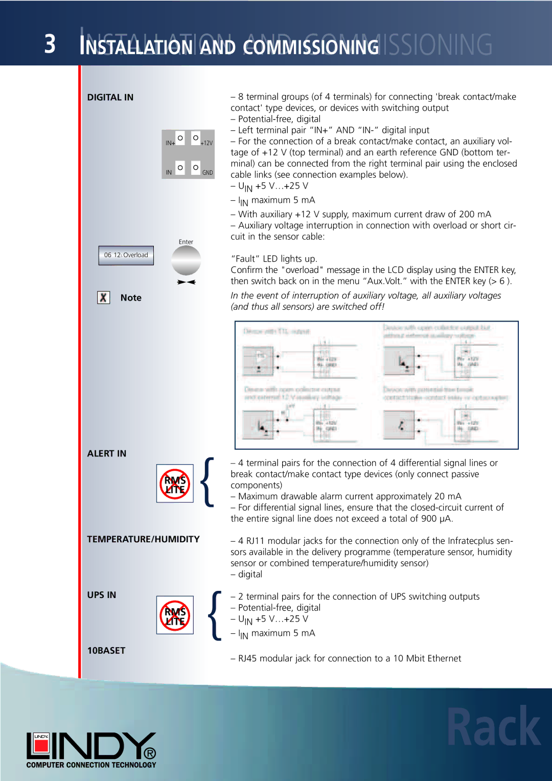
| cable links (see connection examples below). | ||
|
|
|
| |||
| – UIN +5 V…+25 V |
| – IIN maximum 5 mA |
| – With auxiliary +12 V supply, maximum current draw of 200 mA |
| – Auxiliary voltage interruption in connection with overload or short cir- |
| cuit in the sensor cable: |
| Enter |
06 12S Overload | “Fault” LED lights up. |
| |
| Confirm the "overload" message in the LCD display using the ENTER key, |
| then switch back on in the menu “Aux.Volt.” with the ENTER key (> 6 ). |
Note | In the event of interruption of auxiliary voltage, all auxiliary voltages |
| (and thus all sensors) are switched off! |
ALERT IN |
| { |
|
| |||
| – 4 terminal pairs for the connection of 4 differential signal lines or | ||||||
|
|
|
| ||||
|
|
|
| ||||
|
| RMS |
| break contact/make contact type devices (only connect passive | |||
|
|
| components) | ||||
|
| LITE |
| ||||
|
|
| – Maximum drawable alarm current approximately 20 mA | ||||
|
|
|
| ||||
|
|
|
| – For differential signal lines, ensure that the | |||
|
|
|
|
|
| the entire signal line does not exceed a total of 900 µA. | |
TEMPERATURE/HUMIDITY |
|
|
|
| – 4 RJ11 modular jacks for the connection only of the Infratecplus sen- | ||
|
|
|
|
|
| sors available in the delivery programme (temperature sensor, humidity | |
|
|
|
|
|
| sensor or combined temperature/humidity sensor) | |
|
|
|
|
|
| – digital | |
UPS IN |
|
|
|
| { | – 2 terminal pairs for the connection of UPS switching outputs | |
|
|
|
| ||||
|
| RMS |
|
| – | ||
|
|
|
| – U +5 V…+25 V | |||
|
| LITE |
|
| |||
|
|
|
| – IININmaximum 5 mA | |||
10BASET |
|
|
| ||||
|
|
|
| – RJ45 modular jack for connection to a 10 Mbit Ethernet | |||
|
|
|
|
|
| ||
|
|
|
|
|
|
|
|