

 3
3
 IINSTALLATIONNSTALLATIONAND ANDCOMMISSIONINGCOMMISSIONING


3.3 | ELECTRICAL INSTALLATION |
|
|
|
|
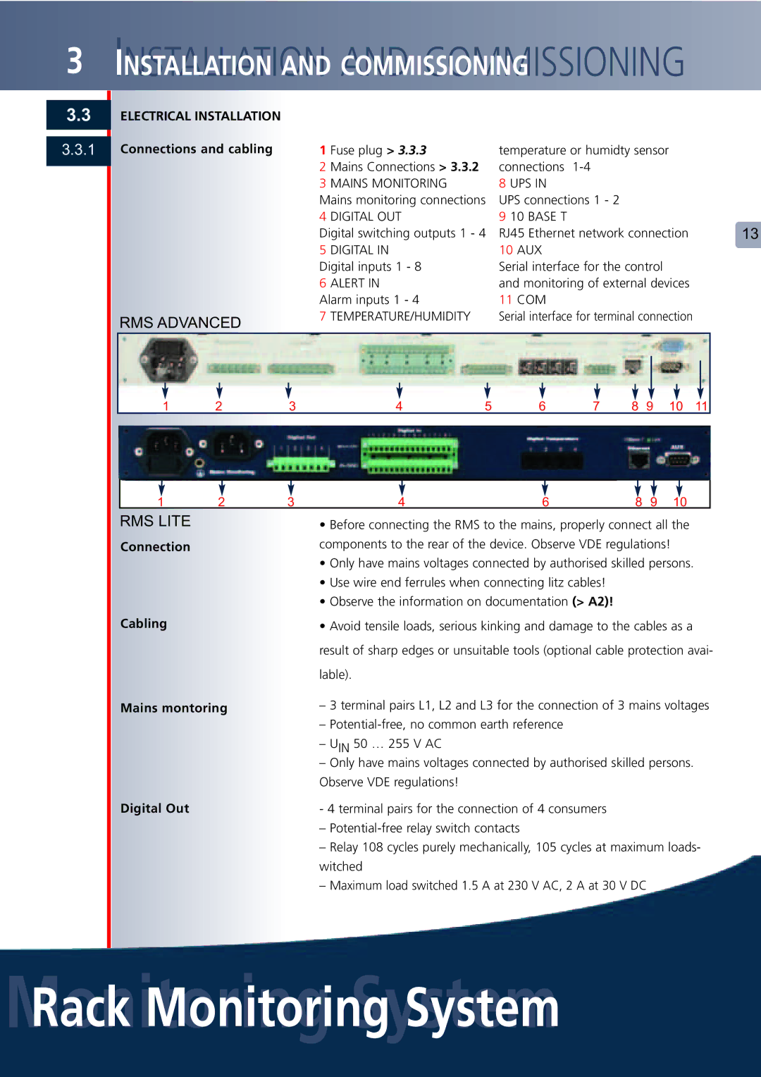
3.3.1 | Connections and cabling | 1 Fuse plug > 3.3.3 | temperature or humidty sensor |
| |
|
| 2 | Mains Connections > 3.3.2 | connections |
|
|
| 3 | MAINS MONITORING | 8 UPS IN |
|
|
| Mains monitoring connections | UPS connections 1 - 2 |
| |
|
| 4 | DIGITAL OUT | 9 10 BASE T |
|
|
| Digital switching outputs 1 - 4 | RJ45 Ethernet network connection | 13 | |
|
| 5 | DIGITAL IN | 10 AUX |
|
|
| Digital inputs 1 - 8 | Serial interface for the control |
| |
|
| 6 | ALERT IN | and monitoring of external devices |
|
|
| Alarm inputs 1 - 4 | 11 COM |
| |
| RMS ADVANCED | 7 | TEMPERATURE/HUMIDITY | Serial interface for terminal connection |
|
|
|
|
|
| |
|
|
|
|
|
|
|
|
|
|
|
|
|
|
|
|
|
|
|
|
|
|
|
|
|
|
|
|
|
|
|
|
|
|
|
|
|
|
|
|
|
|
|
|
|
|
|
|
|
|
|
|
|
|
|
|
|
|
|
|
|
|
|
|
|
|
|
|
|
|
|
|
|
|
|
|
|
|
|
|
|
|
|
|
1 | 2 | 3 | 4 | 5 | 6 | 7 | 8 | 9 | 10 | 11 | ||||||||||
1 | 2 | 3 | 4 | 6 | 8 | 9 | 10 |
RMS LITE |
|
| • Before connecting the RMS to the mains, properly connect all the | ||||
Connection |
|
| components to the rear of the device. Observe VDE regulations! |
| |||
•Only have mains voltages connected by authorised skilled persons.
•Use wire end ferrules when connecting litz cables!
•Observe the information on documentation (> A2)!
Cabling | • Avoid tensile loads, serious kinking and damage to the cables as a |
| result of sharp edges or unsuitable tools (optional cable protection avai- |
| lable). |
Mains montoring | – 3 terminal pairs L1, L2 and L3 for the connection of 3 mains voltages |
| – |
| – UIN 50 … 255 V AC |
| – Only have mains voltages connected by authorised skilled persons. |
| Observe VDE regulations! |
Digital Out | - 4 terminal pairs for the connection of 4 consumers |
| – |
| – Relay 108 cycles purely mechanically, 105 cycles at maximum loads- |
| witched |
| – Maximum load switched 1.5 A at 230 V AC, 2 A at 30 V DC |
