![]()
![]()
![]() 3
3
![]()
![]() IINSTALLATIONNSTALLATIONAND ANDCOMMISSIONINGCOMMISSIONING
IINSTALLATIONNSTALLATIONAND ANDCOMMISSIONINGCOMMISSIONING![]()
![]()
![]()
![]()
COM |
|
|
|
|
|
|
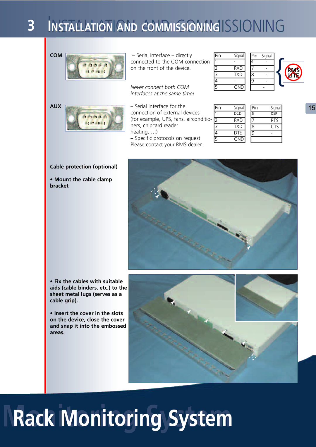
| – Serial interface – directly | Pin | Signal |
| Pin | Signal | { |
|
|
| ||
|
| 1 | 2 | 3 | 4 |
| 5 |
| connected to the COM connection | 1 | - |
| 6 | - |
|
|
| ||
|
|
|
|
|
|
|
| ||||||||||||
|
|
|
| on the front of the device. | 2 | RXD |
| 7 | - |
| RMS |
| |||||||
|
| 6 |
| 7 | 8 | 9 |
|
|
|
|
| ||||||||
|
|
|
|
|
| 3 | TXD |
| 8 | - |
|
| |||||||
|
|
|
|
|
|
|
|
|
|
|
| LITE |
| ||||||
|
|
|
|
|
|
|
|
| Never connect both COM | 4 | - |
| 9 | - |
|
|
| ||
|
|
|
|
|
|
|
|
|
|
|
|
| |||||||
|
|
|
|
|
|
|
|
|
|
|
|
|
|
| |||||
|
|
|
|
|
|
|
|
| 5 | GND |
|
| - |
|
| ||||
AUX |
|
|
|
|
|
|
|
| interfaces at the same time! |
|
|
|
|
|
|
|
|
|
|
|
|
|
|
|
|
| – Serial interface for the |
|
|
|
|
|
|
|
|
|
| ||
|
|
|
|
|
|
|
| Pin | Signal |
| Pin | Signal |
|
| 15 | ||||
|
|
|
|
|
|
|
|
| connection of external devices |
|
|
| |||||||
|
|
|
|
|
|
|
|
| 1 | DCD |
| 6 | DSR |
|
|
|
| ||
| 1 | 2 | 3 | 4 |
| 5 |
| (for example, UPS, fans, airconditio- |
|
|
|
|
|
|
|
|
|
| |
|
| 2 | RXD |
| 7 | RTS |
|
|
|
| |||||||||
| 6 |
| 7 | 8 | 9 |
|
|
|
|
|
|
| |||||||
|
|
|
| ners, chipcard reader |
|
|
|
|
|
|
|
|
|
| |||||
|
|
| 3 | TXD |
| 8 | CTS |
|
|
|
| ||||||||
|
|
|
|
|
|
|
|
|
|
|
|
|
| ||||||
|
|
|
|
|
|
|
|
| heating, …) |
|
|
|
|
|
|
|
|
|
|
|
|
|
|
|
|
|
| 4 | DTE |
| 9 | - |
|
|
|
|
| ||
|
|
|
|
|
|
|
|
|
|
|
|
|
|
| |||||
|
|
|
|
|
|
|
|
| – Specific protocols on request. |
|
|
|
|
|
|
|
|
|
|
|
|
|
|
|
|
|
| 5 | GND |
|
|
|
|
|
|
|
| ||
|
|
|
|
|
|
|
|
| Please contact your RMS dealer. |
|
|
|
|
|
|
|
|
|
|
|
|
|
|
|
|
|
|
|
|
|
|
|
|
|
|
|
| ||
Cable protection (optional)
•Mount the cable clamp bracket
•Fix the cables with suitable
aids (cable binders, etc.) to the sheet metal lugs (serves as a cable grip).
• Insert the cover in the slots on the device, close the cover and snap it into the embossed areas.