![]()
![]()
![]() 4
4![]()
![]()
4.1
RMS
ADVANCED
RMS LITE
OOPERATIONPERATION


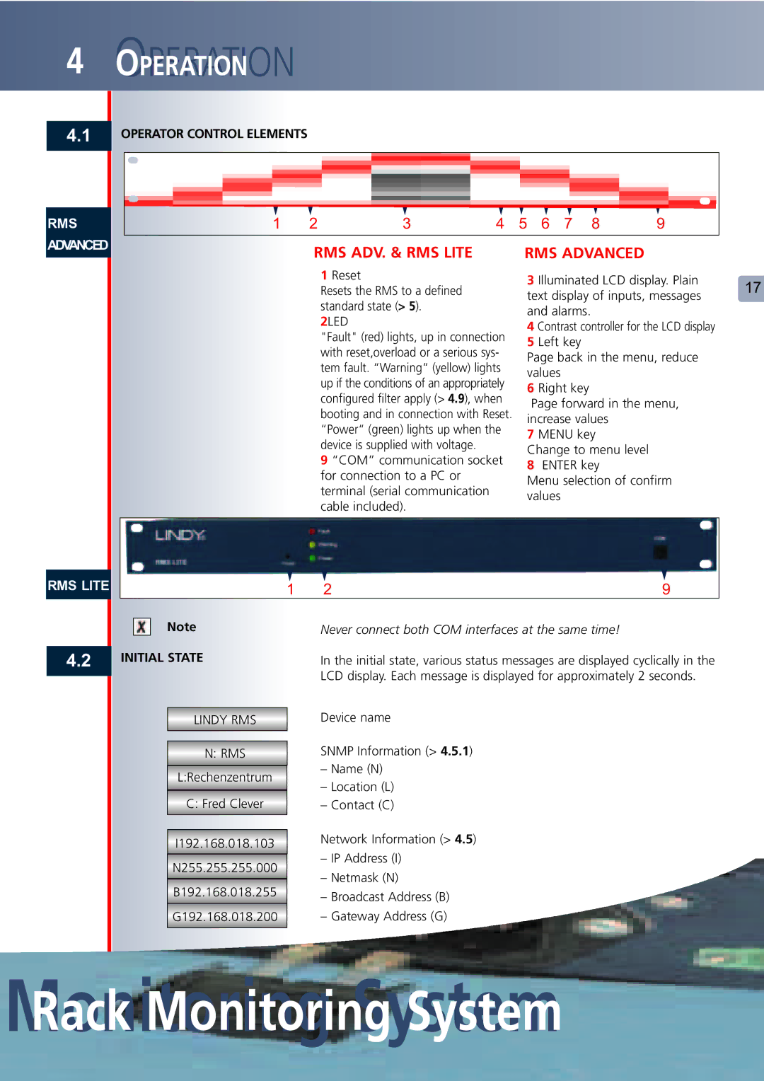
OPERATOR CONTROL ELEMENTS
1 | 2 | 3 | 4 | 5 | 6 | 7 | 8 | 9 |
|
|
|
|
|
|
| ||||
| RMS ADV. & RMS LITE |
| RMS ADVANCED |
|
| ||||
|
| 1 Reset |
| 3 Illuminated LCD display. Plain | 17 | ||||
|
| Resets the RMS to a defined |
| ||||||
|
|
| text display of inputs, messages | ||||||
|
| standard state (> 5). |
|
| |||||
|
|
| and alarms. |
|
|
| |||
|
| 2LED |
|
|
|
| |||
|
|
| 4 Contrast controller for the LCD display |
| |||||
|
| "Fault" (red) lights, up in connection |
| ||||||
|
| 5 Left key |
|
|
| ||||
|
| with reset,overload or a serious sys- |
|
|
| ||||
|
| Page back in the menu, reduce |
| ||||||
|
| tem fault. “Warning“ (yellow) lights |
| ||||||
|
| values |
|
|
|
| |||
|
| up if the conditions of an appropriately |
|
|
|
| |||
|
| 6 Right key |
|
|
| ||||
|
| configured filter apply (> 4.9), when |
|
|
| ||||
|
|
| Page forward in the menu, |
| |||||
|
| booting and in connection with Reset. |
|
| |||||
|
| increase values |
|
| |||||
|
| “Power“ (green) lights up when the |
|
| |||||
|
| 7 MENU key |
|
| |||||
|
| device is supplied with voltage. |
|
|
| ||||
|
|
| Change to menu level |
|
| ||||
|
| 9 “COM” communication socket |
|
| |||||
|
| 8 ENTER key |
|
| |||||
|
| for connection to a PC or |
|
|
| ||||
|
|
| Menu selection of confirm |
| |||||
|
| terminal (serial communication |
|
| |||||
|
|
| values |
|
|
|
| ||
|
| cable included). |
|
|
|
|
| ||
|
|
|
|
|
|
|
|
| |
1 | 2 | 9 |
4.2
Note
INITIAL STATE
LINDY RMS
N: RMS
L:Rechenzentrum
C: Fred Clever
I192.168.018.103
N255.255.255.000
B192.168.018.255
G192.168.018.200
Never connect both COM interfaces at the same time!
In the initial state, various status messages are displayed cyclically in the LCD display. Each message is displayed for approximately 2 seconds.
Device name
SNMP Information (> 4.5.1)
–Name (N)
–Location (L)
–Contact (C)
Network Information (> 4.5)
–IP Address (I)
–Netmask (N)
–Broadcast Address (B)
–Gateway Address (G)