Maxon SP200/210 Radio | SP20/210 |
All further adjustments require the use of the
Refer to the
OSCILLOSCOPE |
RADIOCOMMUNICATIONS
TEST SET
SERIAL DATA
DEMOD
AUDIO
AUDIO IN |
|
|
Power ATE | TXD RXD | |
|
| |
INTERFACE | ATE | AUDIO PTT |
BOX |
|
|
Power
AUDIO OUT ![]()
AF IN AF OUT
DC POWER SUPPLY
SERIAL DATA
7.5VDC @ 2.4A max.
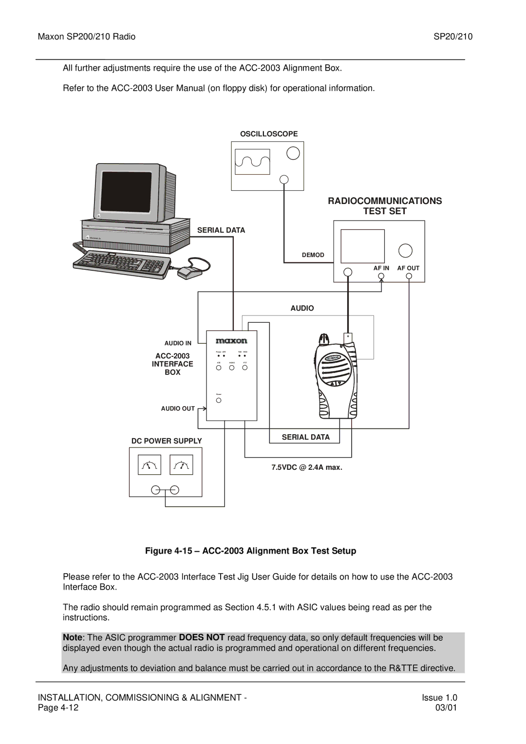
Figure 4-15 – ACC-2003 Alignment Box Test Setup
Please refer to the
The radio should remain programmed as Section 4.5.1 with ASIC values being read as per the instructions.
Note: The ASIC programmer DOES NOT read frequency data, so only default frequencies will be displayed even though the actual radio is programmed and operational on different frequencies.
Any adjustments to deviation and balance must be carried out in accordance to the R&TTE directive.
INSTALLATION, COMMISSIONING & ALIGNMENT - | Issue 1.0 |
Page | 03/01 |