SP200/210 | Maxon SP200/210 Radio |
SK 3100 Service Kit
1 ![]()
2 | 4 |
|
3 ![]()
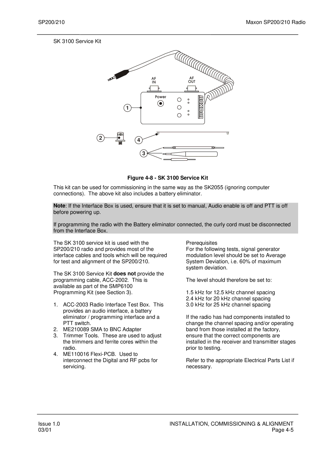
Figure 4-8 - SK 3100 Service Kit
This kit can be used for commissioning in the same way as the SK2055 (ignoring computer connections). The above kit also includes a battery eliminator.
Note: If the Interface Box is used, ensure that it is set to manual, Audio enable is off and PTT is off before powering up.
If programming the radio with the Battery eliminator connected, the curly cord must be disconnected from the Interface Box.
The SK 3100 service kit is used with the SP200/210 radio and provides most of the interface cables and tools which will be required for test and alignment of the SP200/210.
The SK 3100 Service Kit does not provide the programming cable,
1.
2.ME210089 SMA to BNC Adapter
3.Trimmer Tools. These are used to adjust the trimmers and ferrite cores within the radio.
4.ME110016
Prerequisites
For the following tests, signal generator modulation level should be set to Average System Deviation, i.e. 60% of maximum system deviation.
The level should therefore be set to:
1.5kHz for 12.5 kHz channel spacing
2.4kHz for 20 kHz channel spacing
3.0kHz for 25 kHz channel spacing
If the radio has had components installed to change the channel spacing and/or operating band from those installed at the factory, ensure that the correct components are installed in the receiver and transmitter stages prior to testing.
Refer to the appropriate Electrical Parts List if necessary.
Issue 1.0 | INSTALLATION, COMMISSIONING & ALIGNMENT |
03/01 | Page |