SP200/210 | Maxon SP200/210 Radio |
4 INSTALLATION, COMMISSIONING & ALIGNMENT
4.1 Installation
The SP200/210 is a
The User should ensure that the batteries are charged before commencing commissioning tests.
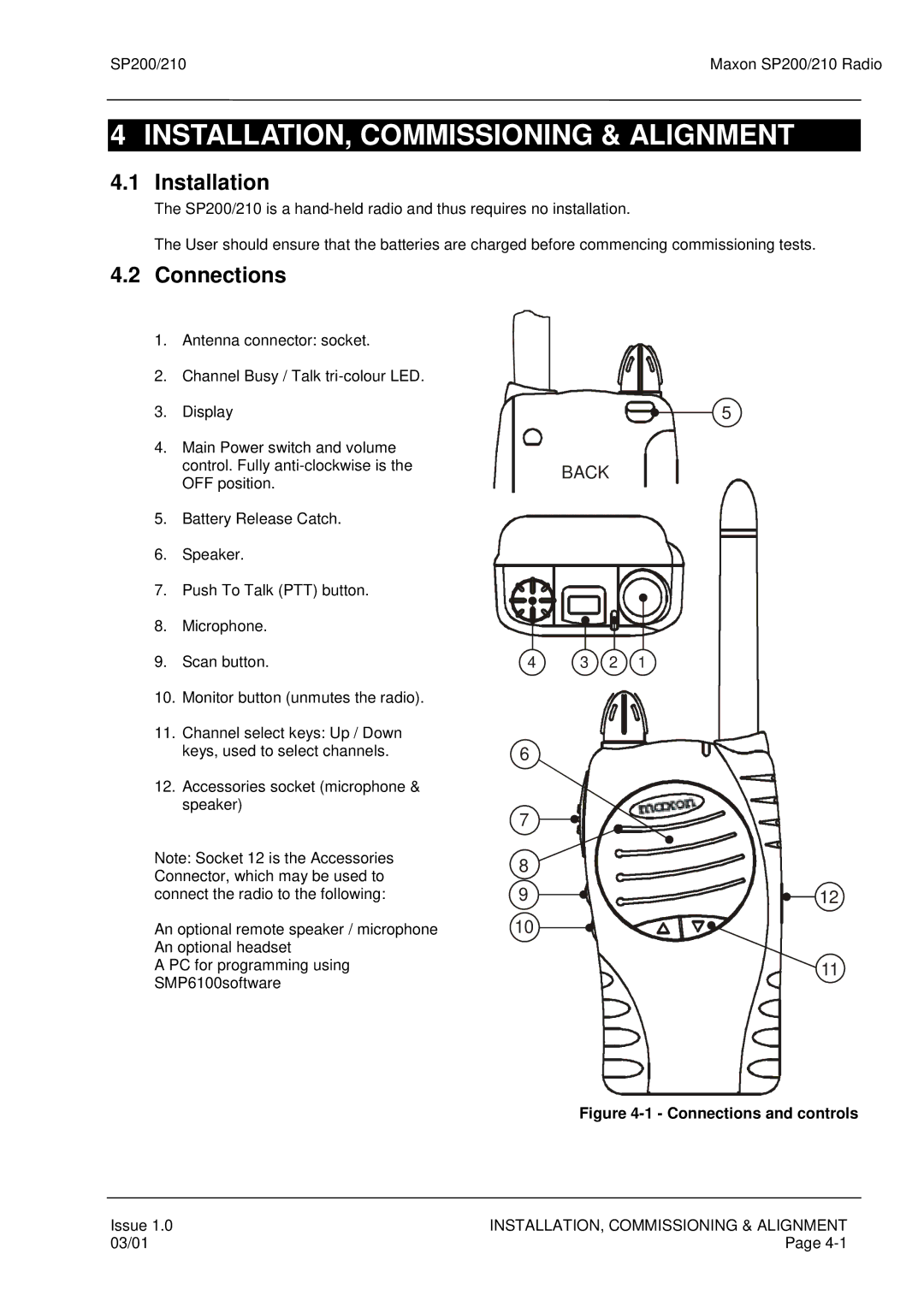
4.2Connections
1.Antenna connector: socket.
2.Channel Busy / Talk
3.Display
4.Main Power switch and volume control. Fully
5.Battery Release Catch.
6.Speaker.
7.Push To Talk (PTT) button.
8.Microphone.
9.Scan button.
10.Monitor button (unmutes the radio).
11.Channel select keys: Up / Down keys, used to select channels.
12.Accessories socket (microphone & speaker)
Note: Socket 12 is the Accessories Connector, which may be used to connect the radio to the following:
An optional remote speaker / microphone An optional headset
A PC for programming using SMP6100software
5
BACK
4 3 2 1
6
7
8
9 ![]()
![]()
![]()
![]()
![]()
![]()
![]()
![]()
![]()
![]()
![]()
![]()
![]()
![]()
![]()
![]() 12
12
10
11
Figure 4-1 - Connections and controls
Issue 1.0 | INSTALLATION, COMMISSIONING & ALIGNMENT |
03/01 | Page |