SP200/210Maxon SP200/210 Radio
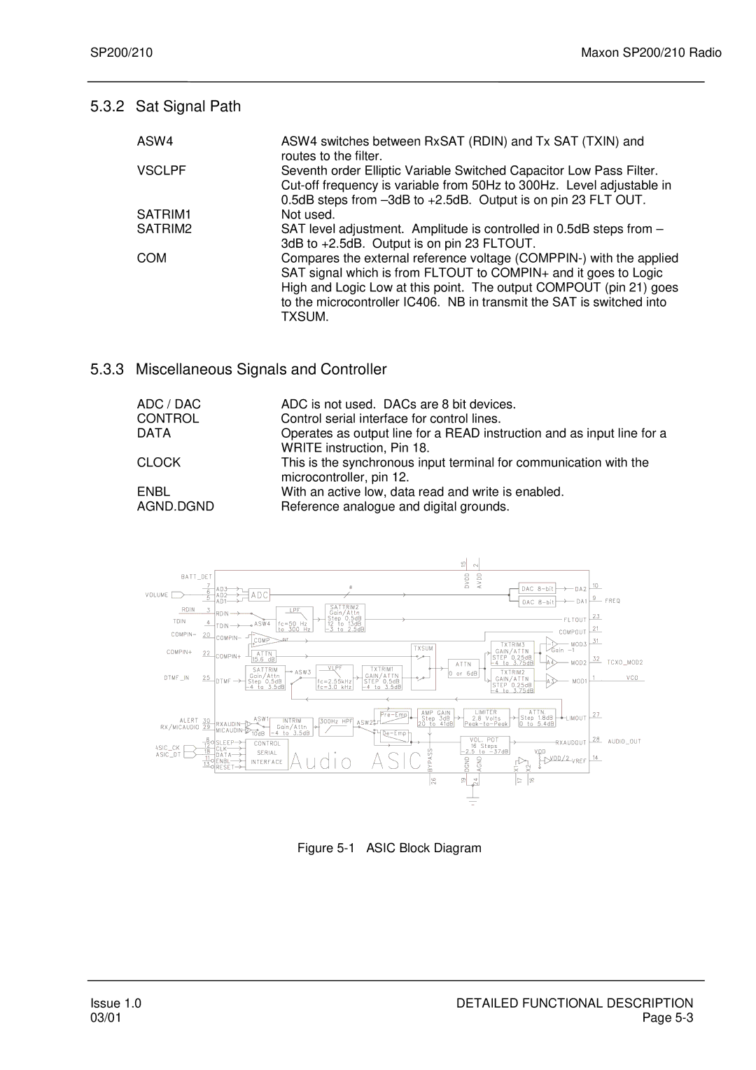
5.3.2 Sat Signal Path
ASW4 | ASW4 switches between RxSAT (RDIN) and Tx SAT (TXIN) and |
| routes to the filter. |
VSCLPF | Seventh order Elliptic Variable Switched Capacitor Low Pass Filter. |
| |
| 0.5dB steps from |
SATRIM1 | Not used. |
SATRIM2 | SAT level adjustment. Amplitude is controlled in 0.5dB steps from – |
| 3dB to +2.5dB. Output is on pin 23 FLTOUT. |
COM | Compares the external reference voltage |
| SAT signal which is from FLTOUT to COMPIN+ and it goes to Logic |
| High and Logic Low at this point. The output COMPOUT (pin 21) goes |
| to the microcontroller IC406. NB in transmit the SAT is switched into |
| TXSUM. |
5.3.3 Miscellaneous Signals and Controller
ADC / DAC |
|
|
|
|
|
|
|
|
| ADC is not used. DACs are 8 bit devices. | |||||||||||||||||||||||||||||||
CONTROL |
|
|
|
|
|
|
|
|
| Control serial interface for control lines. | |||||||||||||||||||||||||||||||
DATA |
|
|
|
|
|
|
|
|
| Operates as output line for a READ instruction and as input line for a | |||||||||||||||||||||||||||||||
|
|
|
|
|
|
|
|
|
| WRITE instruction, Pin 18. | |||||||||||||||||||||||||||||||
CLOCK |
|
|
|
|
|
|
|
|
| This is the synchronous input terminal for communication with the | |||||||||||||||||||||||||||||||
|
|
|
|
|
|
|
|
|
| microcontroller, pin 12. | |||||||||||||||||||||||||||||||
ENBL |
|
|
|
|
|
|
|
|
| With an active low, data read and write is enabled. | |||||||||||||||||||||||||||||||
AGND.DGND |
|
|
|
|
|
|
|
|
| Reference analogue and digital grounds. | |||||||||||||||||||||||||||||||
|
|
|
|
|
|
|
|
|
|
|
|
|
|
|
|
|
|
|
|
|
|
|
|
|
|
|
|
|
|
|
|
|
|
|
|
|
|
|
|
|
|
|
|
|
|
|
|
|
|
|
|
|
|
|
|
|
|
|
|
|
|
|
|
|
|
|
|
|
|
|
|
|
|
|
|
|
|
|
|
|
|
|
|
|
|
|
|
|
|
|
|
|
|
|
|
|
|
|
|
|
|
|
|
|
|
|
|
|
|
|
|
|
|
|
|
|
|
|
|
|
|
|
|
|
|
|
|
|
|
|
|
|
|
|
|
|
|
|
|
|
|
|
|
|
|
|
|
|
|
|
|
|
|
|
|
|
|
|
|
|
|
|
|
|
|
|
|
|
|
|
|
|
|
|
|
|
|
|
|
|
|
|
|
|
|
|
|
|
|
|
|
|
|
|
|
|
|
|
|
|
|
|
|
|
|
|
|
|
|
|
|
|
|
|
|
|
|
|
|
|
|
|
|
|
|
|
|
|
|
|
|
|
|
|
|
|
|
|
|
|
|
|
|
|
|
|
|
|
|
|
|
|
|
|
|
|
|
|
|
|
|
|
|
|
|
|
|
|
|
|
|
|
|
|
|
|
|
|
|
|
|
|
|
|
|
|
|
|
|
|
|
|
|
|
|
|
|
|
|
|
|
|
|
|
|
|
|
|
|
|
|
|
|
|
|
|
|
|
|
|
|
|
|
|
|
|
|
|
|
|
|
|
|
|
|
|
|
|
|
|
|
|
|
|
|
|
|
|
|
|
|
|
|
|
|
|
|
|
|
|
|
|
|
|
|
|
|
|
|
|
|
|
|
|
|
|
|
|
|
|
|
|
|
|
|
|
|
|
|
|
|
|
|
|
|
|
|
|
|
|
|
|
|
|
|
|
|
|
|
|
|
|
|
|
|
|
|
|
|
|
|
|
|
|
|
|
|
|
|
|
|
|
|
|
|
|
|
|
|
|
|
|
|
|
|
|
|
|
|
|
|
|
|
|
|
|
|
|
|
|
|
|
|
|
|
|
|
|
|
|
|
|
|
|
|
|
|
|
|
|
|
|
|
|
|
|
|
|
|
|
|
|
|
|
|
|
|
|
|
|
|
|
|
|
|
|
|
|
|
|
|
|
|
|
|
|
|
|
|
|
|
|
|
|
|
|
|
|
|
|
|
|
|
|
|
|
|
|
|
|
|
|
|
|
|
|
|
|
|
|
|
|
|
|
|
|
|
|
|
|
|
|
|
|
|
|
|
|
|
|
|
|
|
|
|
|
|
|
|
|
|
|
|
|
|
|
|
|
|
|
|
|
|
|
|
|
|
|
|
|
|
|
|
|
|
|
|
|
|
|
|
|
|
|
|
|
|
|
|
|
|
|
|
|
|
|
|
|
|
|
|
|
|
|
|
|
|
|
|
|
|
|
|
|
|
|
|
|
|
|
|
|
|
|
|
|
|
|
|
|
|
|
|
|
|
|
|
|
|
|
|
|
|
|
|
|
|
|
|
|
|
|
|
|
|
|
|
|
|
|
|
|
|
|
|
|
|
|
|
|
|
|
|
|
|
|
|
|
|
|
|
|
|
|
|
|
|
|
|
|
|
|
|
|
|
|
|
|
|
|
|
|
|
|
|
|
|
|
|
|
|
|
|
|
|
|
|
|
|
|
|
|
|
|
|
|
|
|
|
|
|
|
|
|
|
|
|
|
|
|
|
|
|
|
|
|
|
|
|
|
|
|
|
|
|
|
|
|
|
|
|
|
|
|
|
|
|
|
|
|
|
|
|
|
|
|
|
|
|
|
|
|
|
|
|
|
|
|
|
|
|
|
|
|
|
|
|
|
|
|
|
|
|
|
|
|
|
|
|
|
|
|
|
|
|
|
|
|
|
|
|
|
|
|
|
|
|
|
|
|
|
|
|
|
|
|
|
|
|
|
|
|
|
|
|
|
|
|
|
|
|
Figure 5-1 – ASIC Block Diagram
Issue 1.0 | DETAILED FUNCTIONAL DESCRIPTION |
03/01 | Page |