Maxon SP200/210 Radio | SP200/210 |
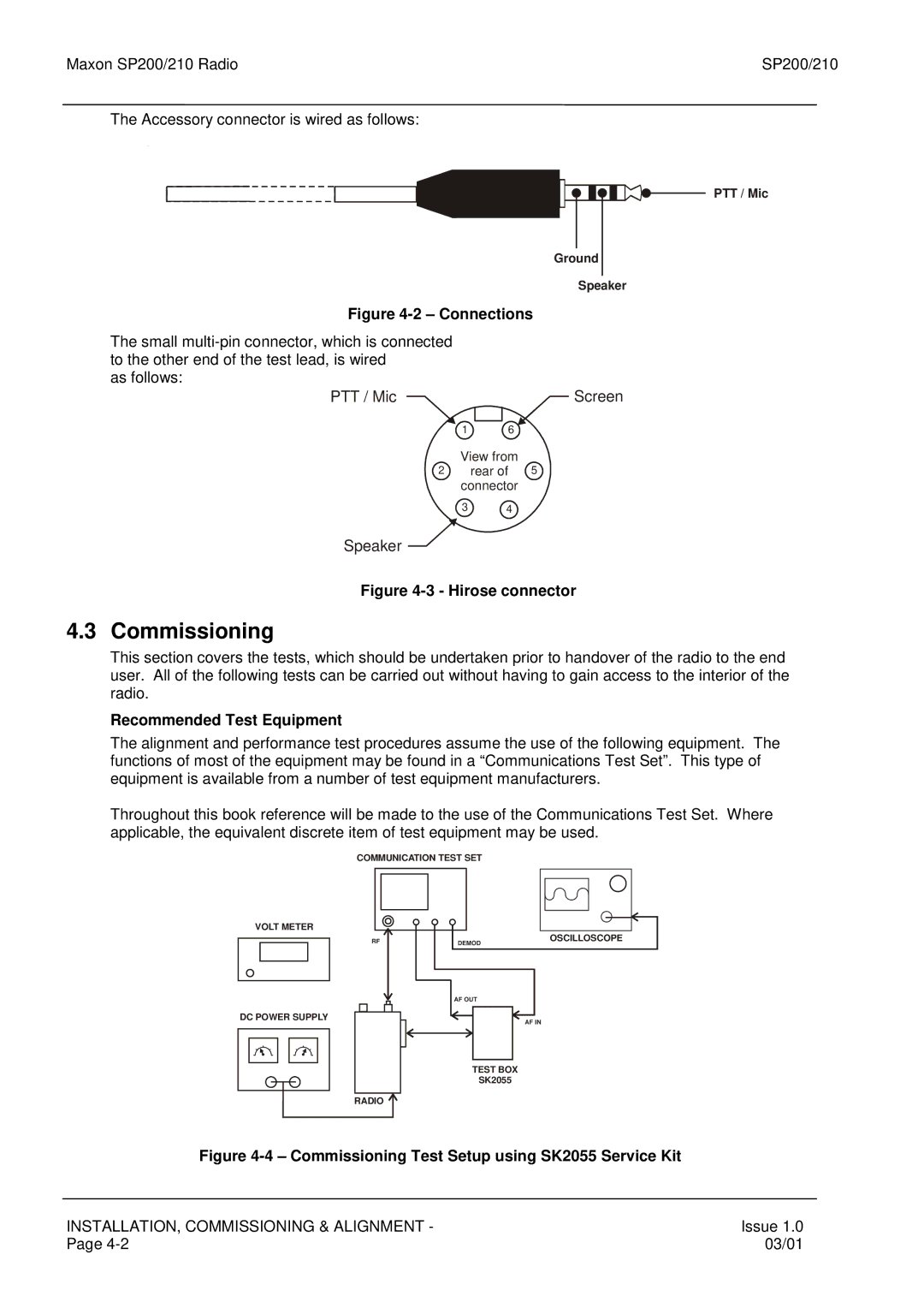
The Accessory connector is wired as follows:
PTT / Mic
Ground
Speaker
Figure 4-2 – Connections
The small
as follows:
PTT / Mic | Screen |
1 | 6 |
View from
2 rear of 5 connector
3 4
Speaker ![]()
Figure 4-3 - Hirose connector
4.3 Commissioning
This section covers the tests, which should be undertaken prior to handover of the radio to the end user. All of the following tests can be carried out without having to gain access to the interior of the radio.
Recommended Test Equipment
The alignment and performance test procedures assume the use of the following equipment. The functions of most of the equipment may be found in a “Communications Test Set”. This type of equipment is available from a number of test equipment manufacturers.
Throughout this book reference will be made to the use of the Communications Test Set. Where applicable, the equivalent discrete item of test equipment may be used.
COMMUNICATION TEST SET
VOLT METER
RF
DC POWER SUPPLY
RADIO ![]()
DEMOD | OSCILLOSCOPE |
|
AF OUT
AF IN
TEST BOX
SK2055
Figure |
|
INSTALLATION, COMMISSIONING & ALIGNMENT - | Issue 1.0 |
Page | 03/01 |