MOUNTING THE LIFT
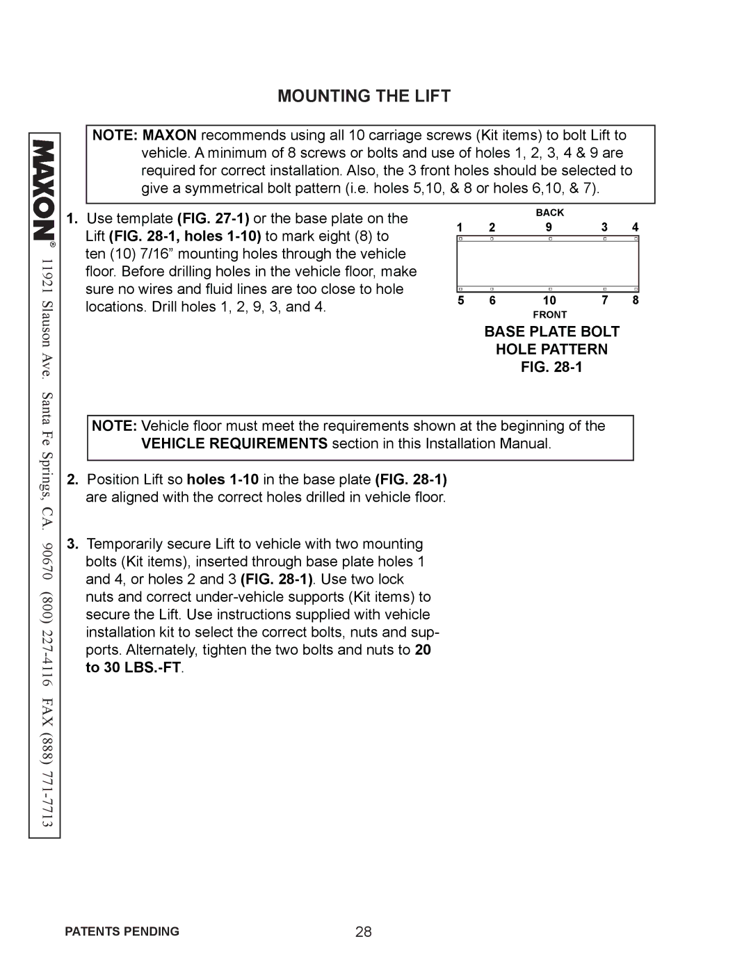
NOTE: MAXON recommends using all 10 carriage screws (Kit items) to bolt Lift to vehicle. A minimum of 8 screws or bolts and use of holes 1, 2, 3, 4 & 9 are required for correct installation. Also, the 3 front holes should be selected to give a symmetrical bolt pattern (i.e. holes 5,10, & 8 or holes 6,10, & 7).
11921
1.Use template (FIG.
|
| BACK |
| 4 |
1 | 2 | 9 | 3 |
5 | 6 | 10 | 7 | 8 |
FRONT
Slauson Ave. Santa Fe Springs, CA. 90670 (800) 227-4116 FAX (888) 771-7713
BASE PLATE BOLT
HOLE PATTERN
FIG.
NOTE: Vehicle floor must meet the requirements shown at the beginning of the VEHICLE REQUIREMENTS section in this Installation Manual.
2.Position Lift so holes
3. Temporarily secure Lift to vehicle with two mounting bolts (Kit items), inserted through base plate holes 1 and 4, or holes 2 and 3 (FIG.
PATENTS PENDING | 28 |