ROUTE/CONNECT CABLES & HAND PENDANT - Continued
11921 Slauson Ave.
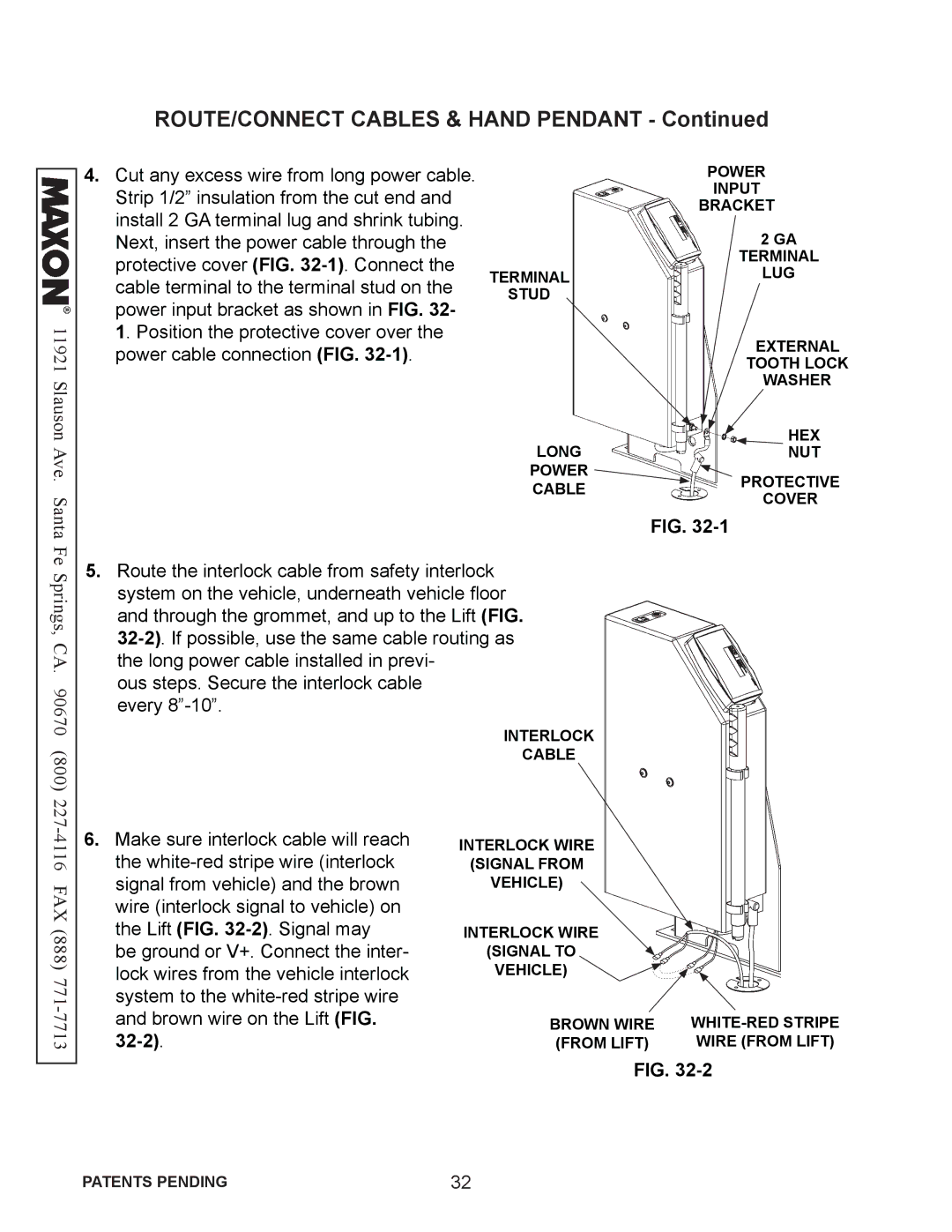
4.Cut any excess wire from long power cable. Strip 1/2” insulation from the cut end and install 2 GA terminal lug and shrink tubing. Next, insert the power cable through the protective cover (FIG.
TERMINAL
STUD
LONG
POWER
CABLE
POWER
INPUT
BRACKET
2GA
TERMINAL
LUG
EXTERNAL
TOOTH LOCK
WASHER
HEX
NUT
PROTECTIVE
COVER
Santa Fe Springs, CA. 90670 (800) 227
FIG.
5.Route the interlock cable from safety interlock system on the vehicle, underneath vehicle floor and through the grommet, and up to the Lift (FIG.
ous steps. Secure the interlock cable every
INTERLOCK
CABLE
6.Make sure interlock cable will reach the
be ground or V+. Connect the inter- lock wires from the vehicle interlock system to the
32-2).
INTERLOCK WIRE
(SIGNAL FROM
VEHICLE)
INTERLOCK WIRE
(SIGNAL TO
VEHICLE)
BROWN WIRE | |
(FROM LIFT) | WIRE (FROM LIFT) |
FIG.
PATENTS PENDING | 32 |
