Maxon Telecom WL7-VERS. C-1K Adjustments, MAT Switch Adjustment if Required

Models: WL7-VERS. C-1K WL7-VERS. C

1 61
Download 61 pages 26.92 Kb
Page 42
Image 42

ADJUSTMENTS

MAT SWITCH ADJUSTMENT (IF REQUIRED)

11921 Slauson Ave.

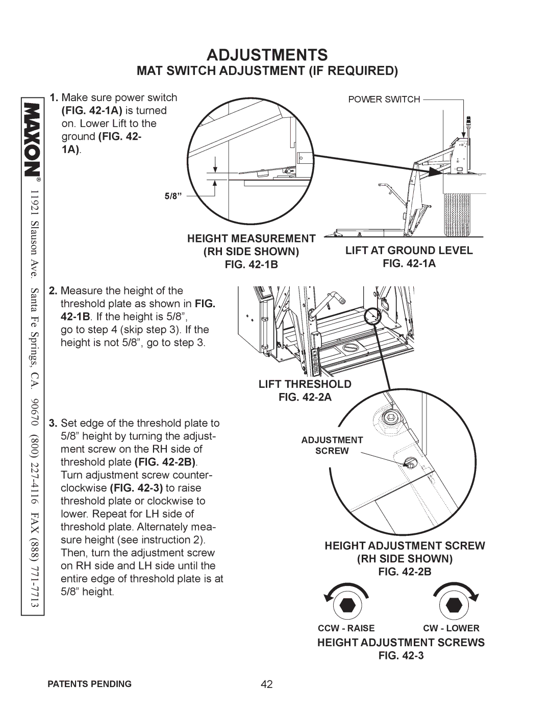
1.Make sure power switch (FIG. 42-1A)is turned on. Lower Lift to the ground (FIG. 42-

1A).

5/8”

HEIGHT MEASUREMENT

(RH SIDE SHOWN)

FIG. 42-1B

POWER SWITCH

LIFT AT GROUND LEVEL

FIG. 42-1A

Santa Fe Springs, CA. 90670 (800) 227-4116 FAX (888) 771-7713

2.Measure the height of the threshold plate as shown in FIG. 42-1B. If the height is 5/8”,

go to step 4 (skip step 3). If the height is not 5/8”, go to step 3.

3.Set edge of the threshold plate to 5/8” height by turning the adjust- ment screw on the RH side of threshold plate (FIG. 42-2B). Turn adjustment screw counter- clockwise (FIG. 42-3)to raise threshold plate or clockwise to lower. Repeat for LH side of threshold plate. Alternately mea- sure height (see instruction 2). Then, turn the adjustment screw on RH side and LH side until the entire edge of threshold plate is at 5/8” height.

LIFT THRESHOLD

FIG. 42-2A

ADJUSTMENT

SCREW

HEIGHT ADJUSTMENT SCREW

(RH SIDE SHOWN)

FIG. 42-2B

CCW - RAISE CW - LOWER

HEIGHT ADJUSTMENT SCREWS

FIG. 42-3

PATENTS PENDING

42

Page 42
Image 42
Maxon Telecom WL7-VERS. C-1K installation instructions Adjustments, MAT Switch Adjustment if Required