1. Presentation
1.2 Overview
1 |
2 |
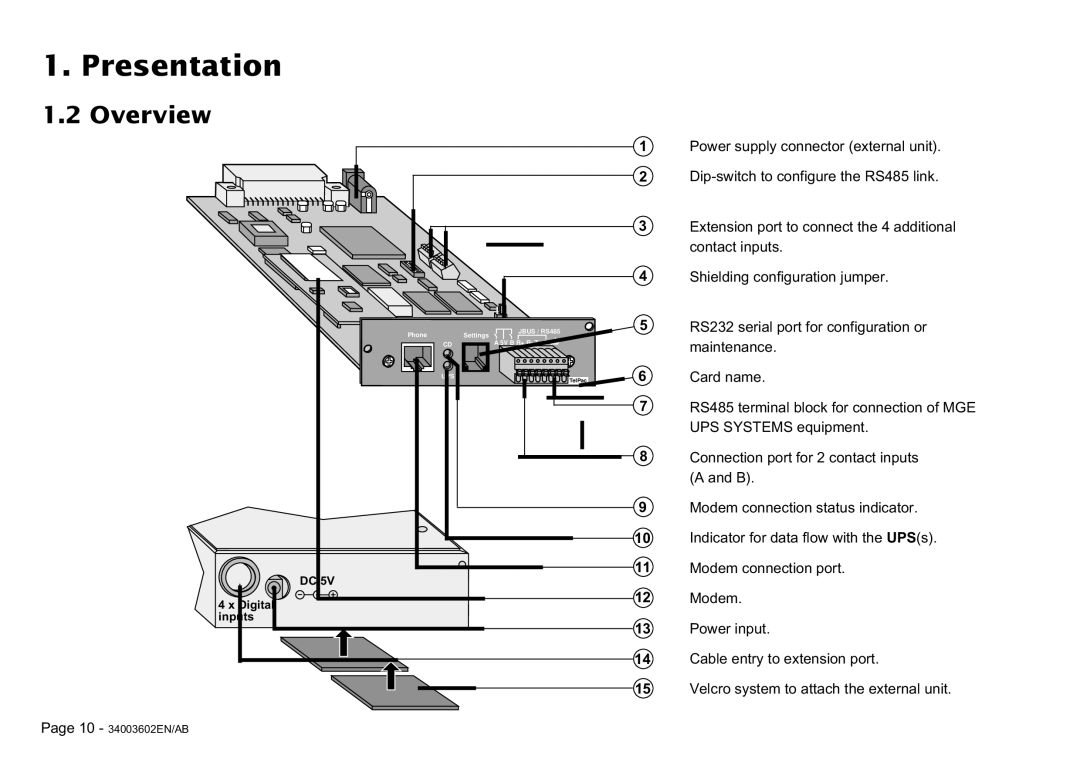
Power supply connector (external unit).
Phone | JBUS / RS485 |
Settings | |
CD | A 5V B R+ R- T+ T- |
UPS | TelPac |
| |
DC 5V |
|
4 x Digital |
|
inputs |
|
3Extension port to connect the 4 additional contact inputs.
4Shielding configuration jumper.
5RS232 serial port for configuration or maintenance.
6Card name.
7RS485 terminal block for connection of MGE UPS SYSTEMS equipment.
8Connection port for 2 contact inputs (A and B).
9Modem connection status indicator.
10Indicator for data flow with the UPS(s).
11Modem connection port.
12Modem.
13Power input.
14Cable entry to extension port.
15Velcro system to attach the external unit.
Page 10 - 34003602EN/AB