2
Hardware Installation 


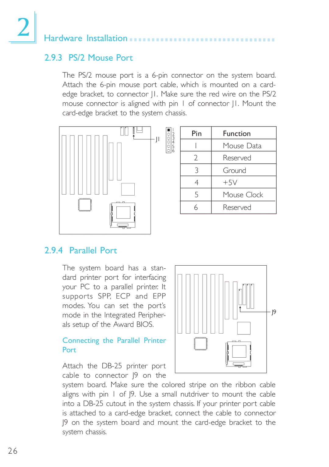
2.9.3 PS/2 Mouse Port
The PS/2 mouse port is a
Pin | Function | |
1 | Mouse Data | |
|
|
|
2 | Reserved | |
|
|
|
3 | Ground | |
|
|
|
4 | +5V | |
|
|
|
5 | Mouse Clock | |
|
|
|
6 | Reserved | |
|
|
|
2.9.4 Parallel Port
The system board has a stan- dard printer port for interfacing your PC to a parallel printer. It supports SPP, ECP and EPP modes. You can set the port’s mode in the Integrated Peripher- als setup of the Award BIOS.
Connecting the Parallel Printer
Port
Attach the
system board. Make sure the colored stripe on the ribbon cable aligns with pin 1 of J9. Use a small nutdriver to mount the cable into a
26