2
Hardware Installation 


2.2 System Memory
2.3DIP Switch and Jumper Settings of the Processors
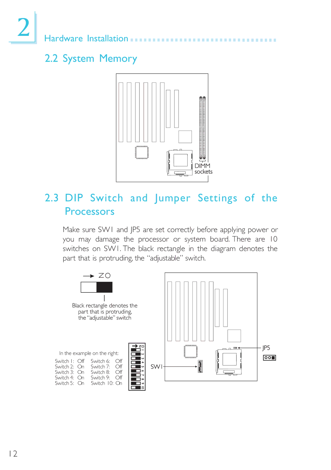
Make sure SW1 and JP5 are set correctly before applying power or you may damage the processor or system board. There are 10 switches on SW1. The black rectangle in the diagram denotes the part that is protruding, the “adjustable” switch.
In the example on the right:
Switch 1: | Off | Switch 6: | Off |
Switch 2: | On | Switch 7: | Off |
Switch 3: | On | Switch 8: | Off |
Switch 4: | On | Switch 9: | Off |
Switch 5: | On | Switch 10: On | |
12