![](/images/new-backgrounds/1171075/17107563x1.webp)
2
Hardware Installation ![](/images/new-backgrounds/1171075/17107563xi2.webp)
![](/images/new-backgrounds/1171075/17107563xi3.webp)
![](/images/new-backgrounds/1171075/17107563xi4.webp)
![](/images/new-backgrounds/1171075/17107563xi5.webp)
![](/images/new-backgrounds/1171075/17107563xi6.webp)
![](/images/new-backgrounds/1171075/17107563xi7.webp)
![](/images/new-backgrounds/1171075/17107563xi8.webp)
![](/images/new-backgrounds/1171075/17107563xi9.webp)
![](/images/new-backgrounds/1171075/17107563xi10.webp)
![](/images/new-backgrounds/1171075/17107563xi11.webp)
![](/images/new-backgrounds/1171075/17107563xi12.webp)
![](/images/new-backgrounds/1171075/17107563xi13.webp)
![](/images/new-backgrounds/1171075/17107563xi14.webp)
![](/images/new-backgrounds/1171075/17107563xi15.webp)
![](/images/new-backgrounds/1171075/17107563xi16.webp)
![](/images/new-backgrounds/1171075/17107563xi17.webp)
![](/images/new-backgrounds/1171075/17107563xi18.webp)
![](/images/new-backgrounds/1171075/17107563xi19.webp)
![](/images/new-backgrounds/1171075/17107563xi20.webp)
![](/images/new-backgrounds/1171075/17107563xi21.webp)
![](/images/new-backgrounds/1171075/17107563xi22.webp)
![](/images/new-backgrounds/1171075/17107563xi23.webp)
![](/images/new-backgrounds/1171075/17107563xi24.webp)
![](/images/new-backgrounds/1171075/17107563xi25.webp)
![](/images/new-backgrounds/1171075/17107563xi26.webp)
![](/images/new-backgrounds/1171075/17107563xi27.webp)
![](/images/new-backgrounds/1171075/17107563xi28.webp)
![](/images/new-backgrounds/1171075/17107563xi29.webp)
![](/images/new-backgrounds/1171075/17107563xi30.webp)
![](/images/new-backgrounds/1171075/17107563xi31.webp)
![](/images/new-backgrounds/1171075/17107563xi32.webp)
![](/images/new-backgrounds/1171075/17107563xi33.webp)
![](/images/new-backgrounds/1171075/17107563xi34.webp)
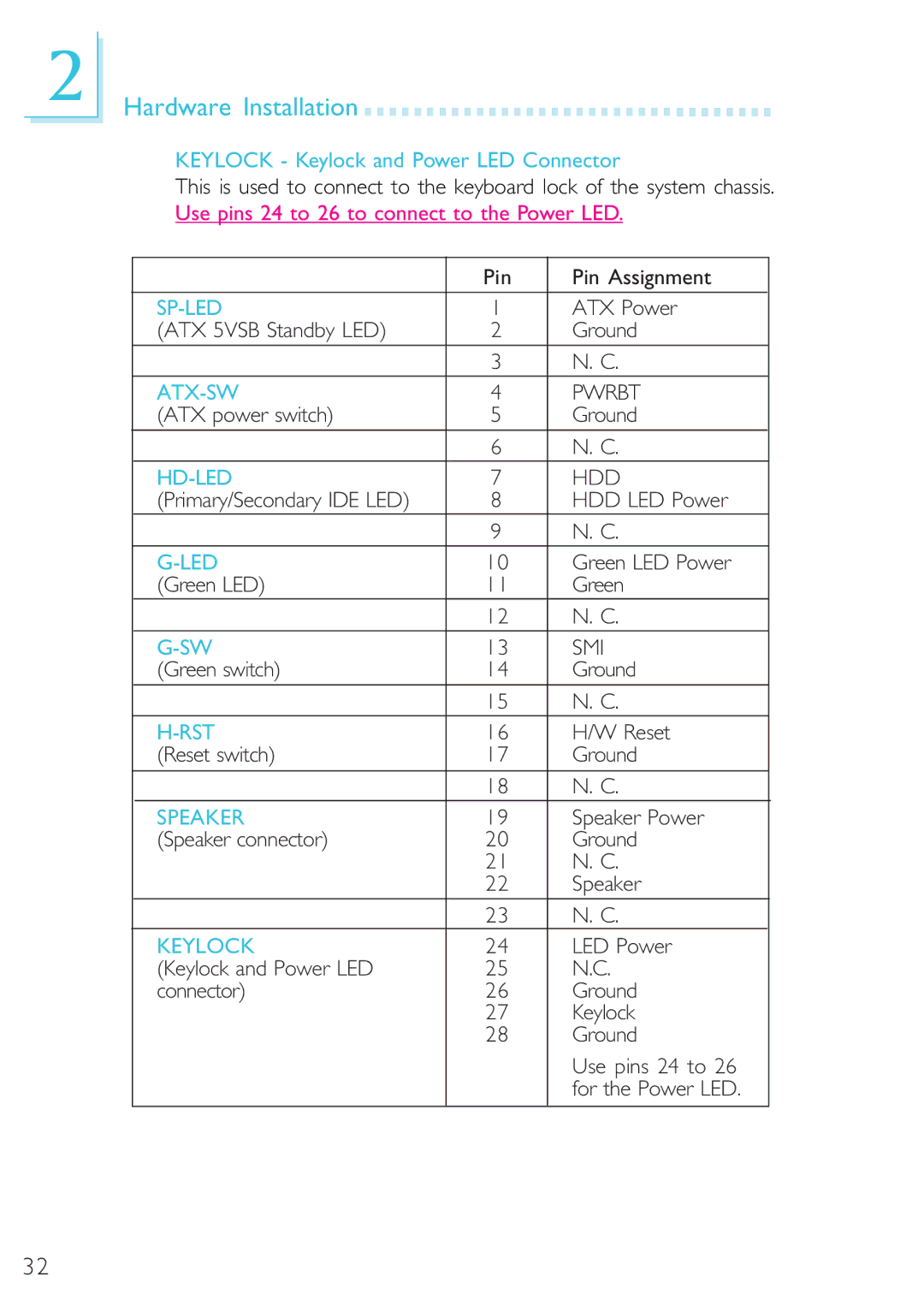
KEYLOCK - Keylock and Power LED Connector
This is used to connect to the keyboard lock of the system chassis. Use pins 24 to 26 to connect to the Power LED.
| Pin | Pin Assignment |
|
|
|
1 | ATX Power | |
(ATX 5VSB Standby LED) | 2 | Ground |
| 3 | N. C. |
4 | PWRBT | |
(ATX power switch) | 5 | Ground |
| 6 | N. C. |
7 | HDD | |
(Primary/Secondary IDE LED) | 8 | HDD LED Power |
| 9 | N. C. |
10 | Green LED Power | |
(Green LED) | 11 | Green |
| 12 | N. C. |
13 | SMI | |
(Green switch) | 14 | Ground |
| 15 | N. C. |
16 | H/W Reset | |
(Reset switch) | 17 | Ground |
| 18 | N. C. |
SPEAKER | 19 | Speaker Power |
(Speaker connector) | 20 | Ground |
| 21 | N. C. |
| 22 | Speaker |
| 23 | N. C. |
KEYLOCK | 24 | LED Power |
(Keylock and Power LED | 25 | N.C. |
connector) | 26 | Ground |
| 27 | Keylock |
| 28 | Ground |
|
| Use pins 24 to 26 |
|
| for the Power LED. |
|
|
|
32