2.5.3 Interrupt Function of the DI Signals
DI0 and DI1 can be used to generate hardware interrupts. Users can setup the configuration of them by programming the interrupt control register.
The channels are connected to the interrupt circuitry. Users can disable/ enable interrupt function, select trigger type or latch the port data by set- ting the Interrupt Control Register of the
2.5.4 IRQ Level
The IRQ level is by default set by the system BIOS. IRQ 7 is reserved for DI interrupt and counter interrupt.
2.5.5 Interrupt Control Register
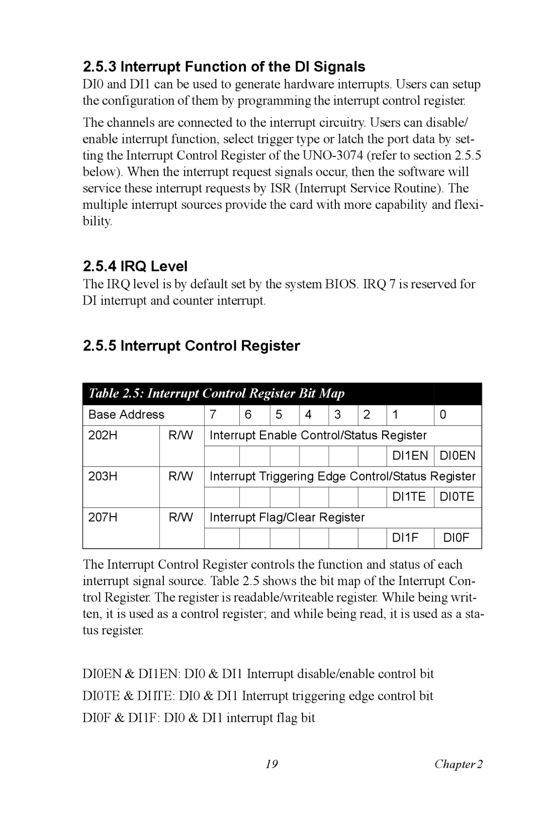
Table 2.5: Interrupt Control Register Bit Map |
|
|
| |||||||
Base Address |
| 7 | 6 | 5 | 4 | 3 | 2 | 1 | 0 | |
|
|
|
|
|
|
|
|
|
| |
202H |
| R/W | Interrupt Enable Control/Status Register |
| ||||||
|
|
|
|
|
|
|
|
|
|
|
|
|
|
|
|
|
|
|
| DI1EN | DI0EN |
|
|
|
|
|
|
|
|
|
|
|
203H |
| R/W | Interrupt Triggering Edge Control/Status Register | |||||||
|
|
|
|
|
|
|
|
|
|
|
|
|
|
|
|
|
|
|
| DI1TE | DI0TE |
|
|
|
|
|
|
|
|
|
|
|
207H |
| R/W | Interrupt Flag/Clear Register |
| ||||||
|
|
|
|
|
|
|
|
|
|
|
|
|
|
|
|
|
|
|
| DI1F | DI0F |
|
|
|
|
|
|
|
|
|
|
|
The Interrupt Control Register controls the function and status of each interrupt signal source. Table 2.5 shows the bit map of the Interrupt Con- trol Register. The register is readable/writeable register. While being writ- ten, it is used as a control register; and while being read, it is used as a sta- tus register.
DI0EN & DI1EN: DI0 & DI1 Interrupt disable/enable control bit
DI0TE & DI1TE: DI0 & DI1 Interrupt triggering edge control bit
DI0F & DI1F: DI0 & DI1 interrupt flag bit
19 | Chapter2 |