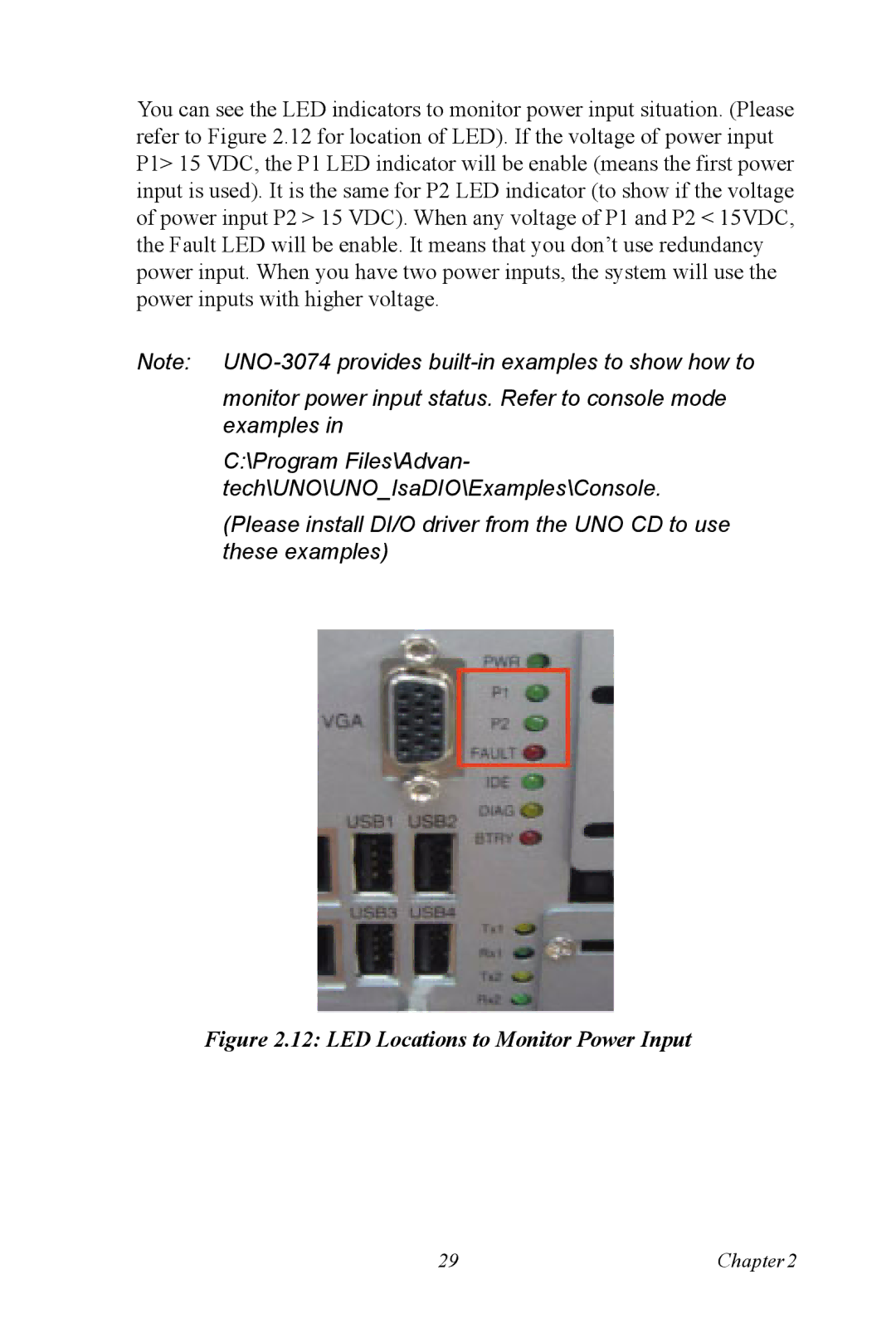
You can see the LED indicators to monitor power input situation. (Please refer to Figure 2.12 for location of LED). If the voltage of power input P1> 15 VDC, the P1 LED indicator will be enable (means the first power input is used). It is the same for P2 LED indicator (to show if the voltage of power input P2 > 15 VDC). When any voltage of P1 and P2 < 15VDC, the Fault LED will be enable. It means that you don’t use redundancy power input. When you have two power inputs, the system will use the power inputs with higher voltage.
Note:
monitor power input status. Refer to console mode examples in
C:\Program Files\Advan-
tech\UNO\UNO_IsaDIO\Examples\Console.
(Please install DI/O driver from the UNO CD to use these examples)
Figure 2.12: LED Locations to Monitor Power Input
29 | Chapter2 |