2.6.2 Power On Configuration
Default configuration after power on or hardware reset is to set all the iso- lated digital output channels to open status (the current of the load can’t be sink) so that users need not worry about damaging external devices during system startup or reset. When the system is hot reset, then the status of iso- lated digital output channels are selected by jumper JP7. Table 2.10 shows the configuration of jumper JP7.
Note: Please refer to Figure A.3 for location of JP7
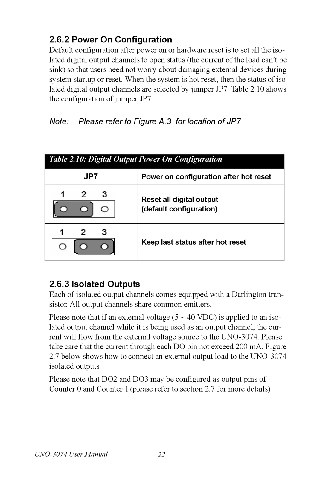
Table 2.10: Digital Output Power On Configuration
JP7 | Power on configuration after hot reset |
|
|
| Reset all digital output |
| (default configuration) |
|
|
| Keep last status after hot reset |
|
|
2.6.3 Isolated Outputs
Each of isolated output channels comes equipped with a Darlington tran- sistor. All output channels share common emitters.
Please note that if an external voltage (5 ~ 40 VDC) is applied to an iso- lated output channel while it is being used as an output channel, the cur- rent will flow from the external voltage source to the
2.7below shows how to connect an external output load to the
Please note that DO2 and DO3 may be configured as output pins of Counter 0 and Counter 1 (please refer to section 2.7 for more details)
22 |