Table 2.4: Digital Input Connector Signal Description
Signal Name | Reference | Direction | Description |
|
|
|
|
DI <0...3> | COM | Input | Isolated DI signals |
|
|
|
|
COM | - | - | DI, DO isolated |
|
|
| ground |
2.5.2 Isolated Inputs
Each of isolated digital input channels accepts 0 ~ 50 VDC voltage inputs, and accepts
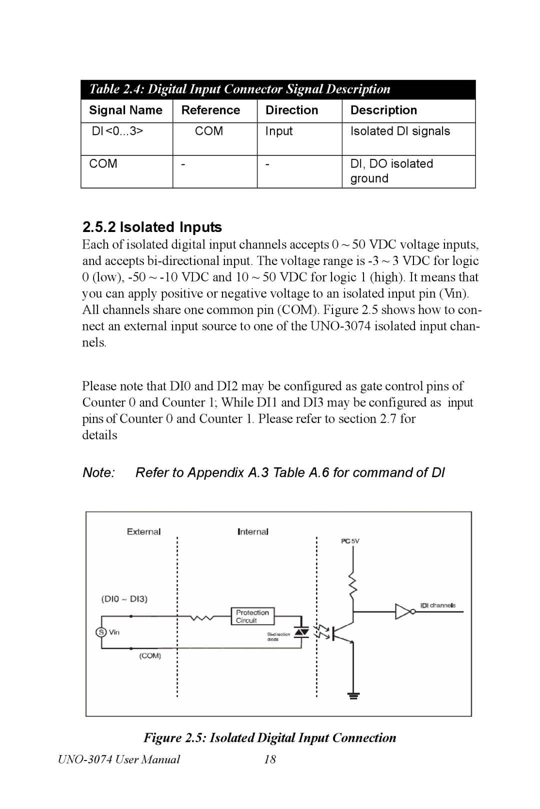
All channels share one common pin (COM). Figure 2.5 shows how to con- nect an external input source to one of the
Please note that DI0 and DI2 may be configured as gate control pins of Counter 0 and Counter 1; While DI1 and DI3 may be configured as input pins of Counter 0 and Counter 1. Please refer to section 2.7 for
details
Note: Refer to Appendix A.3 Table A.6 for command of DI
Figure 2.5: Isolated Digital Input Connection
18 |