Table 2.18: Power Register Bit Map
218H R
Power Register
PWR P2 P1
PWR | =0, Power fail | |
|
| =1, Power normal |
P1 | (24V) | =0, Power input 1 fail |
|
| =1, Power input 1 normal |
P2 | (24V*) | =0, Power input 2 fail |
|
| =1, Power input 2 normal |
2.9 LED and Buzzer for System Diagnosis
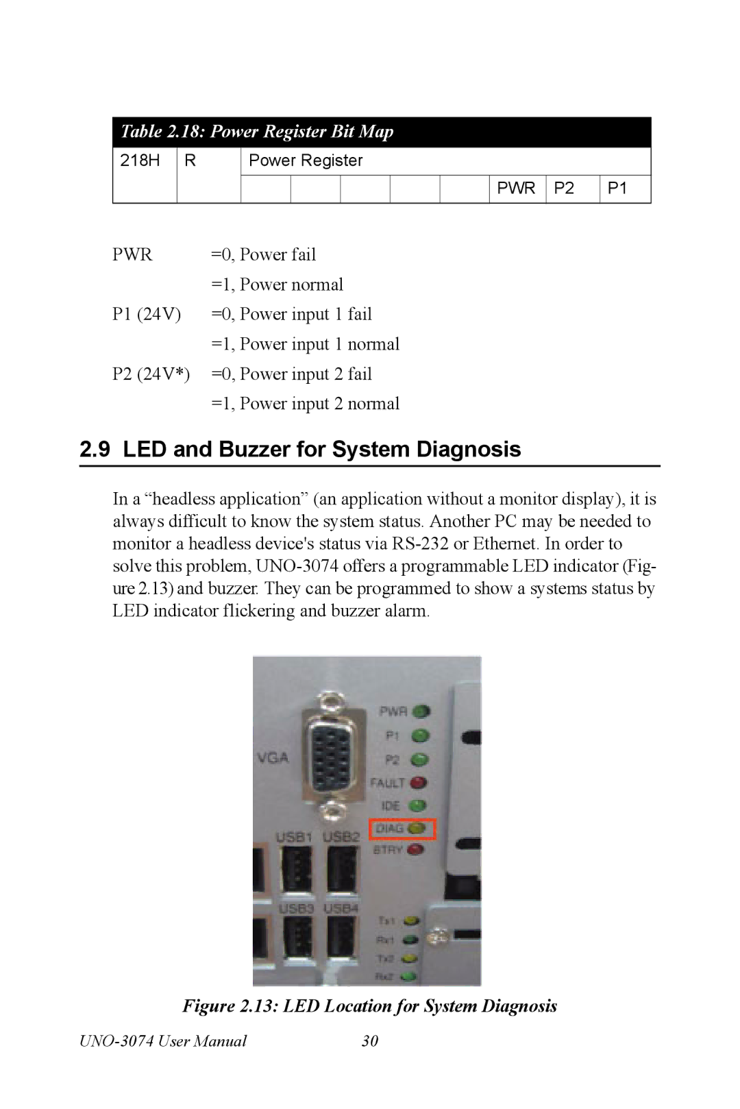
In a “headless application” (an application without a monitor display), it is always difficult to know the system status. Another PC may be needed to monitor a headless device's status via
Figure 2.13: LED Location for System Diagnosis
30 |