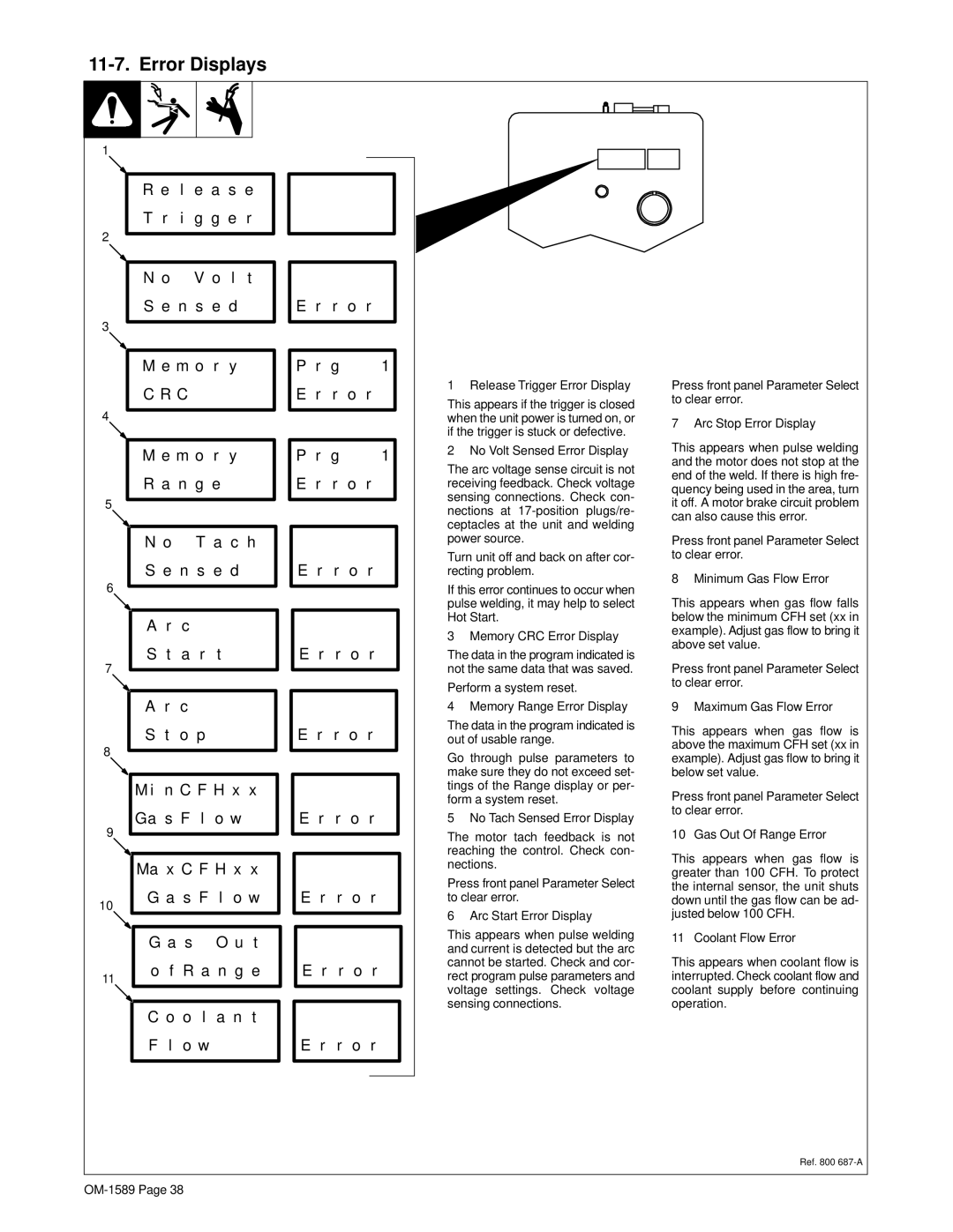
11-7. Error Displays
1
R e l e a s e
T r i g g e r
2
N o V o l t
S e n s e d
3
M e m o r y
C R C
4
M e m o r y
R a n g e
5
|
| N o | T a c h |
| ||
|
| S e n s e d |
| |||
6 |
|
|
|
|
|
|
|
|
|
|
|
| |
|
|
|
|
|
|
|
|
| A | r | c |
|
|
7 |
| S | t | a r | t |
|
|
|
|
|
|
| |
|
|
|
|
|
| |
|
|
|
|
|
|
|
|
| A | r | c |
|
|
|
| S | t | o p |
|
|
8 |
|
|
|
|
|
|
|
|
|
|
|
| |
|
|
|
|
| ||
|
| M i | n C F H x x |
| ||
9 |
| Ga s F l | o w |
| ||
|
|
|
|
|
| |
|
|
|
|
|
| |
|
|
|
| |||
|
| Ma x C F H x x |
| |||
10 |
| G a s F | l o w |
| ||
|
|
|
|
|
| |
|
|
|
|
| ||
|
| G a s | O u t |
| ||
11 |
| o f R a n g e |
| |||
|
|
|
|
|
| |
|
|
|
|
|
| |
|
| C o | o l | a n t |
| |
|
| F | l | o w |
|
|
|
|
|
|
|
|
|
E | r | r | o | r |
|
|
|
|
|
|
|
|
|
|
P | r | g |
| 1 |
E | r | r | o | r |
|
|
|
|
|
|
|
|
|
|
P | r | g |
| 1 |
E | r | r | o | r |
|
|
|
|
|
E r r o r
E r r o r
E r r o r
E r r o r
E r r o r
E r r o r
E r r o r
1 Release Trigger Error Display
This appears if the trigger is closed when the unit power is turned on, or if the trigger is stuck or defective.
2 No Volt Sensed Error Display
The arc voltage sense circuit is not receiving feedback. Check voltage sensing connections. Check con- nections at
Turn unit off and back on after cor- recting problem.
If this error continues to occur when pulse welding, it may help to select Hot Start.
3 Memory CRC Error Display
The data in the program indicated is not the same data that was saved.
Perform a system reset.
4 Memory Range Error Display
The data in the program indicated is out of usable range.
Go through pulse parameters to make sure they do not exceed set- tings of the Range display or per- form a system reset.
5 No Tach Sensed Error Display
The motor tach feedback is not reaching the control. Check con- nections.
Press front panel Parameter Select to clear error.
6 Arc Start Error Display
This appears when pulse welding and current is detected but the arc cannot be started. Check and cor- rect program pulse parameters and voltage settings. Check voltage sensing connections.
Press front panel Parameter Select to clear error.
7 Arc Stop Error Display
This appears when pulse welding and the motor does not stop at the end of the weld. If there is high fre- quency being used in the area, turn it off. A motor brake circuit problem can also cause this error.
Press front panel Parameter Select to clear error.
8 Minimum Gas Flow Error
This appears when gas flow falls below the minimum CFH set (xx in example). Adjust gas flow to bring it above set value.
Press front panel Parameter Select to clear error.
9 Maximum Gas Flow Error
This appears when gas flow is above the maximum CFH set (xx in example). Adjust gas flow to bring it below set value.
Press front panel Parameter Select to clear error.
10 Gas Out Of Range Error
This appears when gas flow is greater than 100 CFH. To protect the internal sensor, the unit shuts down until the gas flow can be ad- justed below 100 CFH.
11 Coolant Flow Error
This appears when coolant flow is interrupted. Check coolant flow and coolant supply before continuing operation.
Ref. 800
