11-8. Using Self Test
Access
Setup
Display
Press
Mode
Select
R e m o t e
A r c | T i m e | |
>S e | l | f T e s t |
W i | r e f e e d | |
1
> S wi t c h | A |
O f f
> S wi t c h | A | |
| O n | |
Gun | Increase | |
Increase | ||
|
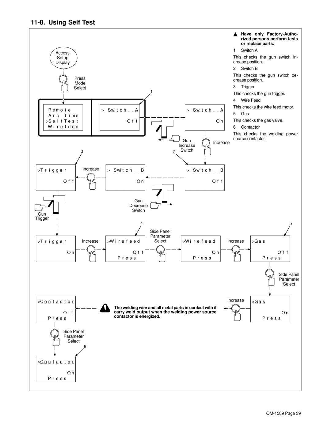
YHave only
1 Switch A
This checks the gun switch in- crease position.
2 Switch B
This checks the gun switch de- crease position.
3 Trigger
This checks the gun trigger.
4 Wire Feed
This checks the wire feed motor.
5 Gas
This checks the gas valve.
6 Contactor
This checks the welding power source contactor.
| 3 |
|
>T r i g g e r | Increase > S wi t c h | B |
O f f |
| O n |
2 | Switch |
|
|
| |
| > S wi t c h | B |
| O f | f |
Gun
Trigger
>T r i g g e r | Increase |
O n
>C o n t a c t o r
Gun
Decrease
Switch
| 4 |
| Side Panel |
| Parameter |
>W i r e f e e d | Select |
O f | f |
P r e s s |
|
>W i r e f e e d
O n
P r e s s
Increase
Increase
5
>G a s
O f f
P r e s s
Side Panel
Parameter
Select
>G a s
O f f
P r e s s
Side Panel
Parameter
Select
6
>C o n t a c t o r
O n
P r e s s
The welding wire and all metal parts in contact with it carry weld output when the welding power source contactor is energized.
O n