4-8. Remote 14 Receptacle RC14 Information and Connections
2
1
|
|
| 3 |
A | K | J I | 4 |
B |
|
|
|
C L N | H |
| |
D | M | G |
|
| E | F |
|
|
|
| |
2
1
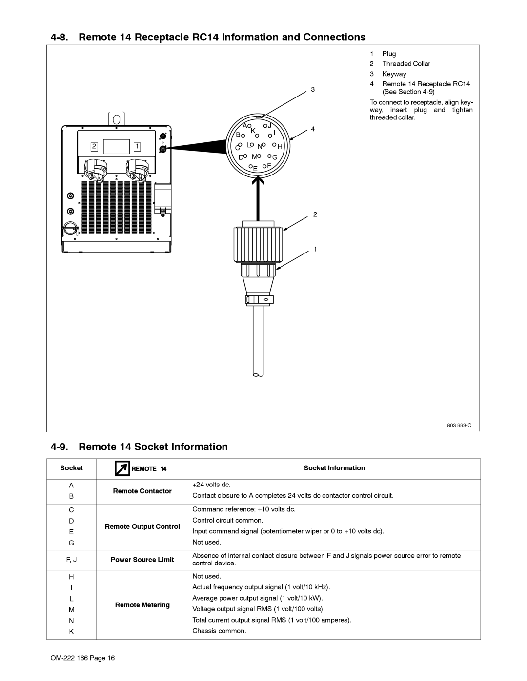
1Plug
2Threaded Collar
3Keyway
4Remote 14 Receptacle RC14 (See Section
To connect to receptacle, align key- way, insert plug and tighten threaded collar.
803
4-9. Remote 14 Socket Information
Socket |
| Socket Information | |
|
|
| |
A | Remote Contactor | +24 volts dc. | |
B | Contact closure to A completes 24 volts dc contactor control circuit. | ||
| |||
|
|
| |
C |
| Command reference; +10 volts dc. | |
D | Remote Output Control | Control circuit common. | |
E | Input command signal (potentiometer wiper or 0 to +10 volts dc). | ||
| |||
G |
| Not used. | |
|
|
| |
F, J | Power Source Limit | Absence of internal contact closure between F and J signals power source error to remote | |
control device. | |||
|
| ||
|
|
| |
H |
| Not used. | |
I |
| Actual frequency output signal (1 volt/10 kHz). | |
L | Remote Metering | Average power output signal (1 volt/10 kW). | |
M | Voltage output signal RMS (1 volt/100 volts). | ||
| |||
N |
| Total current output signal RMS (1 volt/100 amperes). | |
K |
| Chassis common. | |
|
|
|