MITSUBISHI | 2033D SERIES UPS | Page Number: |
ELECTRIC | OWNERS / TECHNICAL MANUAL |
1.3Overview
The UPS provides two power paths between the utility source and the critical load.
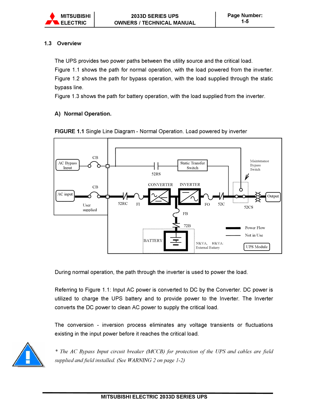
Figure 1.1 shows the path for normal operation, with the load powered from the inverter. Figure 1.2 shows the path for bypass operation, with the load supplied through the static bypass line.
Figure 1.3 shows the path for battery operation, with the load supplied from the inverter.
A) Normal Operation.
FIGURE 1.1 Single Line Diagram - Normal Operation. Load powered by inverter
CB
AC Bypass
Input
CB
AC input
User supplied
|
| Static Transfer |
| Maintenance |
|
|
| Bypass | |
|
| Switch |
| |
|
|
| Switch | |
| 52RS |
|
| |
|
|
|
| |
| CONVERTER | INVERTER |
|
|
|
|
|
| Output |
52RC | FI | FO | 52C | 52CS |
|
|
|
| |
|
| FB |
|
|
|
| 72B |
| Power Flow |
|
|
|
| |
| BATTERY |
|
| Not in Use |
| 50kVA, | 80kVA: |
| |
|
| UPS Module | ||
|
| External Battery | ||
During normal operation, the path through the inverter is used to power the load.
Referring to Figure 1.1: Input AC power is converted to DC by the Converter. DC power is utilized to charge the UPS battery and to provide power to the Inverter. The Inverter converts the DC power to clean AC power to supply the critical load.
The conversion - inversion process eliminates any voltage transients or fluctuations existing in the input power before it reaches the critical load.
*The AC Bypass Input circuit breaker (MCCB) for protection of the UPS and cables are field supplied and field installed. (See WARNING 2 on page
MITSUBISHI ELECTRIC 2033D SERIES UPS