DX-TL5000E
Features
Beginning
Unplug the Power Cord During a Long Absence
Installation Location and Handling
Contents
System Menu
73-75
77-81
82-87
Flowchart
Flowchart for connection and settings
Setting the motion detection
Setting the timer recording
Timer recording is executed and completed
Searching the recorded data
Major operations and their functions
Busy indicator
DET DOT ON/OFF/M-DET Area SET UP Camera Number 9
Camera control buttons
Output A/B button
Front view inside of the door Power button
Video OUT connector
SET UP button
Timer button
Main switch
AC power socket
Camera connectors
Video Cascade connectors
Alarm in terminals
Alarm OUT terminals
Reset button
16. RS485 IN/OUT connectors
Precautions for installation
Precautions for attaching or removing the HDD
Connections
Connections
Connecting to Cctv camera, monitor, and sensor
Connections
Alarm recording connection
Cascade connection
Cascade OUT
When removing a HDD
Attaching or removing the HDD
Fix the metal part with four screws Attach the front covers
When attaching a HDD
Attach the new HDD onto the HDD tray with four screws
English
Connecting to an analogue video cassette recorder
Clamping the cables
Attaching the optional board
Optional items
Recommended items
How to set the menus
Setting the menus
How to set a menu with a mouse Setting a mouse
Setting a menu with a mouse
Selecting an item
Displaying a menu screen
Closing a menu screen
When you use the buttons on the unit
When you use a mouse
Setting parameters
Inputting numbers
Symbols in the menus
Buttons on the unit
Setup Wizard
Setup Wizard
Setup wizard is displayed, in order to set up an indispen
Power button on the front panel
Set the HDD configuration
When selecting Partition Set the desired partition capacity
Select whether or not to make the recording settings
Select Finish to exit setup wizard
Menu chart
Menu chart
User Menu 100 000
+ D Go
Menu chart
Menu chart
Setup Menu 200 000
English
Emergency Recording Setup 215 000
Multiplexer Setting 245 000
Menu chart
System Menu 300 000
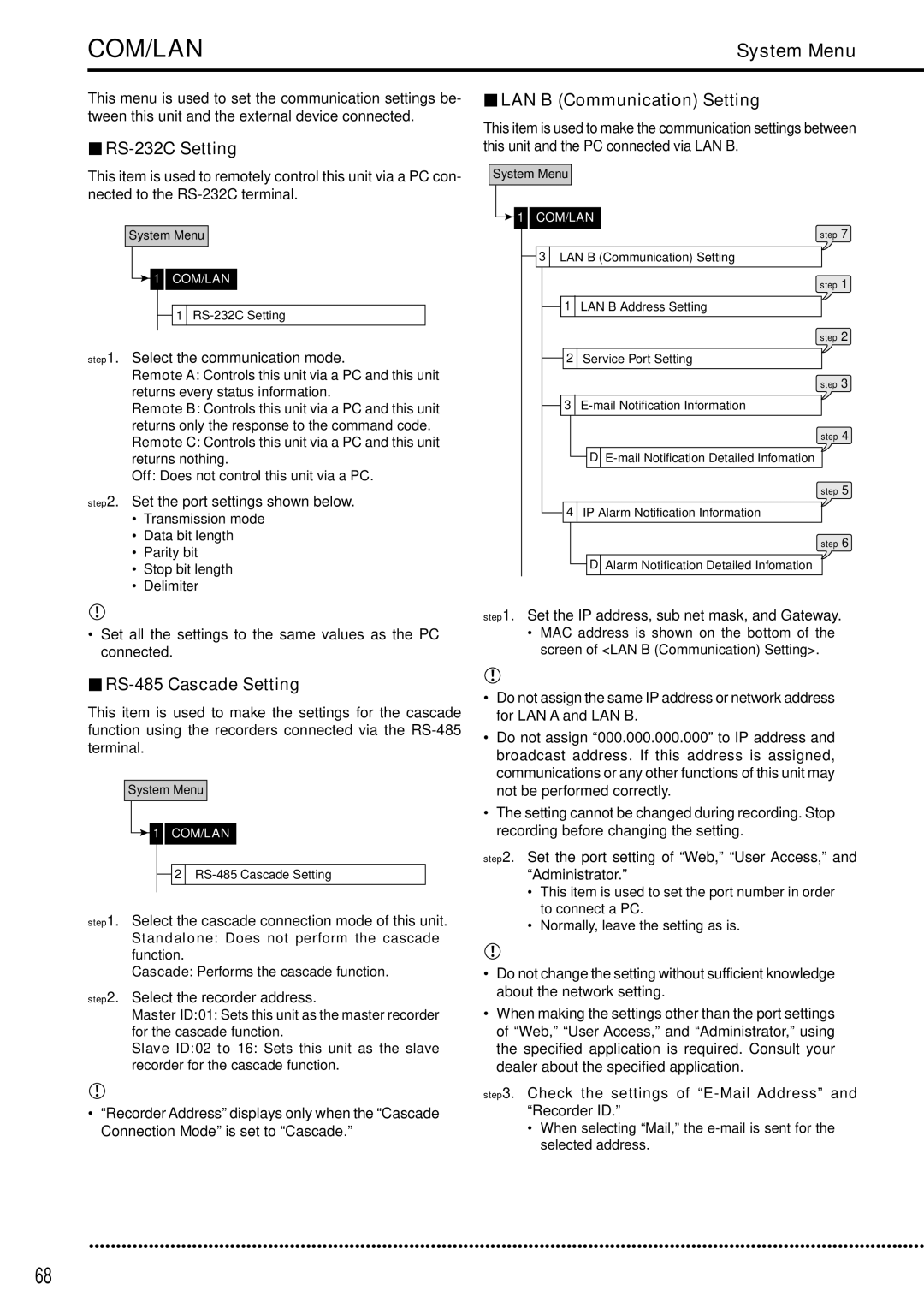
COM/LAN
Exit Exits the Service Info menu
Registers or removes the USB device for main or copy
Search
Search by Motion
Set the motion detection conditions for playback
Operations
Steps 1, 2
Copy Data to Copy B Drive/Set Copy B Drive
Copy
Copy Data to Copy a Drive/Set Copy a Drive
Playback software
Copying the data of this unit to a video cassette
Information/Audio
Information
Audio
Main Storage Memory Information
Protect Data
Protect Data
Set the start and end points of the data to be locked
Example
Settings concerning normal recording and alarm recording
Pre-alarm recording
Recording
Set Recording Pattern a to D
Normal recording settings
Alarm recording settings
Set the alarm mode
Set the pre-alarm recording time in Pre-Alarm Duration
Alarm recording
Alarm Input
Set the recording camera for each sensor connected
Frame recording and field recording
Emergency recording
Emergency Recording Setup
Long pre-alarm recording
Audio Recording Setup
Set the audio recording setting for each channel, 1 to
Set the audio recording mode
Area with the pictures. See pages 74
Timer
Timer
Setting the program
Carrying out timer recording
Overlapped timer settings
Example
Steps 1, 3, 4, 5
Motion Det
Set the reference interval time
Motion Det
Time/Date Setting
System
Menu Language Selection
Set the present date, month, year, hour, minute, and second
Rear Terminal Setting
Mode Out Settings
Mode Out 1 to
Low Memory Alarm Setting
Set the desired buzzer setting
Key Sound
Set the key sound to on or off
Buzzer
Password Setting
Activating the Password Lock
Releasing the Password Lock For the levels 1
Changing the Password
Changing the lock mode from Password Lock to
To cancel the sequential display
Camera number button operations
Split buttons operations
Sequence button operations
Operations
Multiplexer Setting
Output a Display Settings
Selectable screen types are shown in the table on
Split screen
Output B Display Settings
Set the covert camera setting for each camera number
Alarm Display Setting
Covert Camera Setting
On Screen Display Setting
Monitor Output Adjust
Audio Setting
Reset to Factory Setting
Save Menu Data
Menu Data
Load Menu Data
RS-485 Cascade Setting
RS-232C Setting
LAN B Communication Setting
LAN a NAS Setting
Select Return in the screen of LAN a NAS Setting
PTZ Setting
PTZ Camera Configuration
Configuration Check List
Select Configuration Check List in the PTZ Setting menu
Elapsed Operating Time
Service Info
System Log List Disk Information
Restore
Set the camera number to be restored
Set the other detailed settings
Set the start, start/end, or end points of restoring
Add or remove the internal HDDs for setting the main device
Add or remove the NAS HDD for setting the copy device
Memory
Add/Remove HDD Device
Data Management Setting for Main Memory
Attaching the HDD and setting the ID number
Memory
Add/Remove DVD/CD Drive
Recording Data Readout Setting
Playback Device Repeat Setting
Image Originality Check Play
Auto-Expire on Specified Date
Copy A/Copy B
Data Clear
Main Storage Memory
To control the other recorder, repeat steps 1 and 2 above
Other convenient functions
Cascade
Control the camera
PTZ control
Press the PTZ button
Various playback functions
Playback the latest recorded contents
Changing playback intervals
Simultaneous playback during recording
Triplex playback
Functions of the unit in case of power failure
Registering the picture
Operation examples
Operation example
Measuring for setting the partition capacity
Settings Alarm area settings see pages 74
Repeat recording settings see pages 74
Set the motion detection settings for Motion B
Recording settings Set Recording Pattern B see pages 46 to
Motion detection settings see pages 53
Timer recording settings see pages 51
Set the motion detection settings for Motion a and Motion B
Set the timer program number to Program
Basic operations
Basic multiplexer functions
Basic manual recording
Basic playback
Repeatedly see
To change the playback device
To stop playback, press the Stop button
Basic search
Search by Time and Date
Search by Alarm List
Personal computer product requirements
Communications by Web Browser Login
Communications by Web Browser
Communications by Web Browser
Main Menu
Live Monitoring
Select the date and time and click Search
Playback
Time Search
Alarm List Search
Configuration Menu
User Registration
Image Search
When you have selected cancel
If you have selected cancel
Mail Setup
Memo & Camera Titles
Select change and left-click
Select set and left-click Select active and left-click
NAS Setup
Select NAS Setup and left-click
Clock Setup
100
Change Login User
101
Logout
Close the Web Browser
Recording time table
102
Continuous recording time table
HDD continuous recording time
103
Troubleshooting
104
Troubleshooting
105
106
107
None
Setup Menu 200 000
Check sheet
108
Recording Set Recording Pattern a
109
Check sheet
110
Set Recording Pattern B
111
112
Set Recording Pattern C
113
114
Set Recording Pattern D
115
Emergency Recording Setup
Audio Recording Setup
Timer Configure Timer Program
116
Motion Det
117
Define Holidays
Rear Terminal Setting
Password Setting
118
System Menu Language Selection
Output a Settings Sequence Time
119
Split 9 screen
Sequence Single Split
Multiplexer Setting
Output B Settings
Alarm Display Setting Output a
120
121
Alarm Display Setting Output B
Covert Camera Setting
122
On Screen Display Setting
Audio Setting
123
System Menu 300 000
PTZ Setting PTZ Camera Configuration
124
Port Pan
Device ID
125
Memory Add/Remove HDD Device/ 2 Add/Remove DVD/CD Drive
Group 4USB device
126
Add/Remove HDD Device Add/Remove DVD/CD Drive
127
Data Management Setting for Main Memory
Recording Data Readout Setting
Glossary
Glossary
128
Glossary
129
Second
130
Specifications
Specifications
Others
Portuges
Tempo de gravação e garantia do produto
Others
Others
Plats FÖR Installation OCH Handhavande
Inspelningstid och produktgaranti
SLD Security & Communications