Parts Name and Functions (continued)
CAT5 Tx BOX
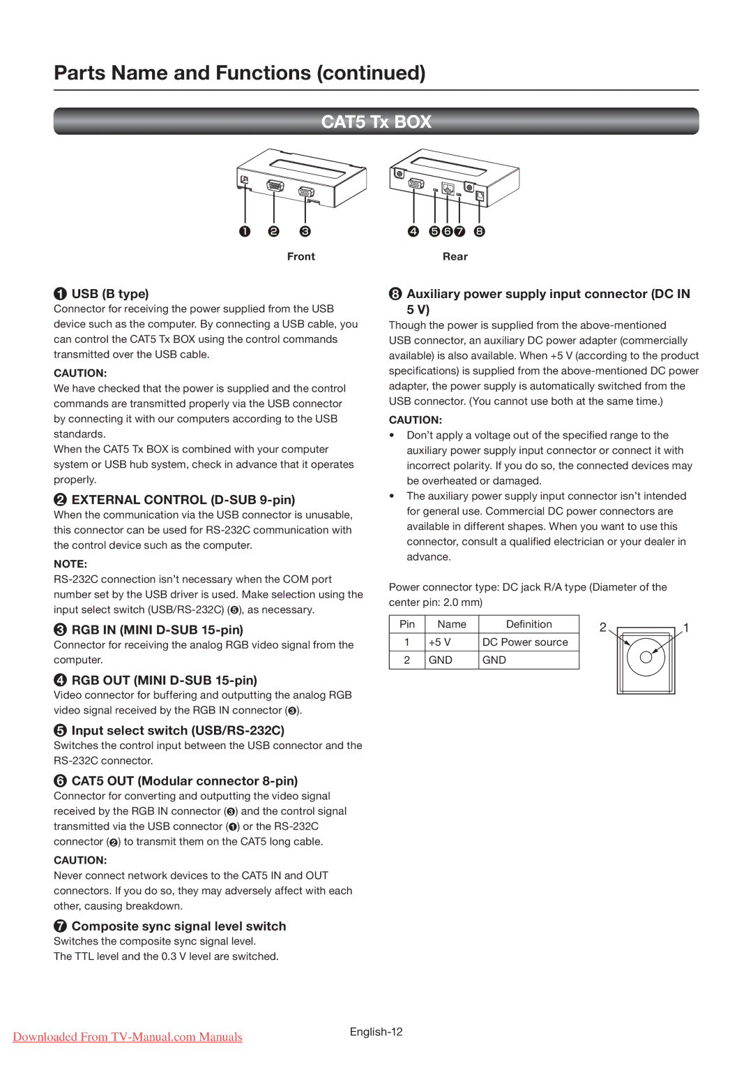
FrontRear
1USB (B type)
Connector for receiving the power supplied from the USB device such as the computer. By connecting a USB cable, you can control the CAT5 Tx BOX using the control commands transmitted over the USB cable.
CAUTION:
We have checked that the power is supplied and the control commands are transmitted properly via the USB connector by connecting it with our computers according to the USB standards.
When the CAT5 Tx BOX is combined with your computer system or USB hub system, check in advance that it operates properly.
2EXTERNAL CONTROL (D-SUB 9-pin)
When the communication via the USB connector is unusable, this connector can be used for
NOTE:
3RGB IN (MINI
Connector for receiving the analog RGB video signal from the computer.
4RGB OUT (MINI
Video connector for buffering and outputting the analog RGB video signal received by the RGB IN connector ( 3 ).
5Input select switch
Switches the control input between the USB connector and the
6CAT5 OUT (Modular connector 8-pin)
Connector for converting and outputting the video signal received by the RGB IN connector ( 3 ) and the control signal transmitted via the USB connector ( 1 ) or the
CAUTION:
Never connect network devices to the CAT5 IN and OUT connectors. If you do so, they may adversely affect with each other, causing breakdown.
7Composite sync signal level switch
Switches the composite sync signal level.
The TTL level and the 0.3 V level are switched.
8Auxiliary power supply input connector (DC IN
5 V)
Though the power is supplied from the
CAUTION:
•Don’t apply a voltage out of the specified range to the auxiliary power supply input connector or connect it with incorrect polarity. If you do so, the connected devices may be overheated or damaged.
•The auxiliary power supply input connector isn’t intended for general use. Commercial DC power connectors are available in different shapes. When you want to use this connector, consult a qualified electrician or your dealer in advance.
Power connector type: DC jack R/A type (Diameter of the
center pin: 2.0 mm)
Pin | Name | Definition | 2 | 1 |
1 | +5 V | DC Power source |
|
|
2 | GND | GND |
|
|
Downloaded From | |
|