Remote control (continued) | Carry out as necessary |
| |
|
|
|
|
2)Control command diagram
The command is structured by the address code, function code, data code and end code. The length of the command is different for each function.
NOTE:
This example shows a basic command that is used when a single computer and a single monitor are connected.
When you want to connect multiple monitors or perform complicated control using other commands than the basic commands, contact your dealer for advanced command specifications.
| Address code | Function code |
| Data code | End code |
| ||
|
|
|
|
|
|
|
| |
HEX |
| 30h 30h | Function |
| Data | 0Dh |
| |
|
|
|
|
|
|
|
| |
ASCII |
| ‘0’ ‘0’ | Function |
| Data |
|
| |
|
|
|
|
|
|
| ||
[Address code] | 30h 30h (ASCII code, ‘0’ ‘0’), fixed. |
|
| |||||
[Function code] | Code unique to each control function. |
|
| |||||
[Data code] |
| Data unique to each control function (Not always indicated by numerical values.) | ||||||
[End code] |
| 0Dh (In ASCII code, ‘ ’) fixed. |
|
|
| |||
3)Control sequence
(1)A command is sent from the computer to the monitor. (Commands should be sent at intervals of at least 600 ms.)
(2)The monitor sends a return command within 600 ms* after receiving and encoding the command. If the monitor fails to receive the command, it doesn’t send any return command.
(3)The computer checks the return command to see that the command it sent was executed or not.
(4)The monitor sends various codes other than the return code. While
codes on the personal computer side.
*: Transmission of the return command may be delayed during signal switchover, etc. Example: Turn the power ON (‘ ’ is for ASCII code)
Command from computer | Command from monitor | Detail of command |
30 30 21 0D |
| Command for POWER ON |
‘0’ ‘0’ ‘!’ ‘ ’ |
| |
|
| |
| 30 30 21 0D | Command received |
| ‘0’ ‘0’ ‘!’ ‘ ’ | (Command echoed back) |
For
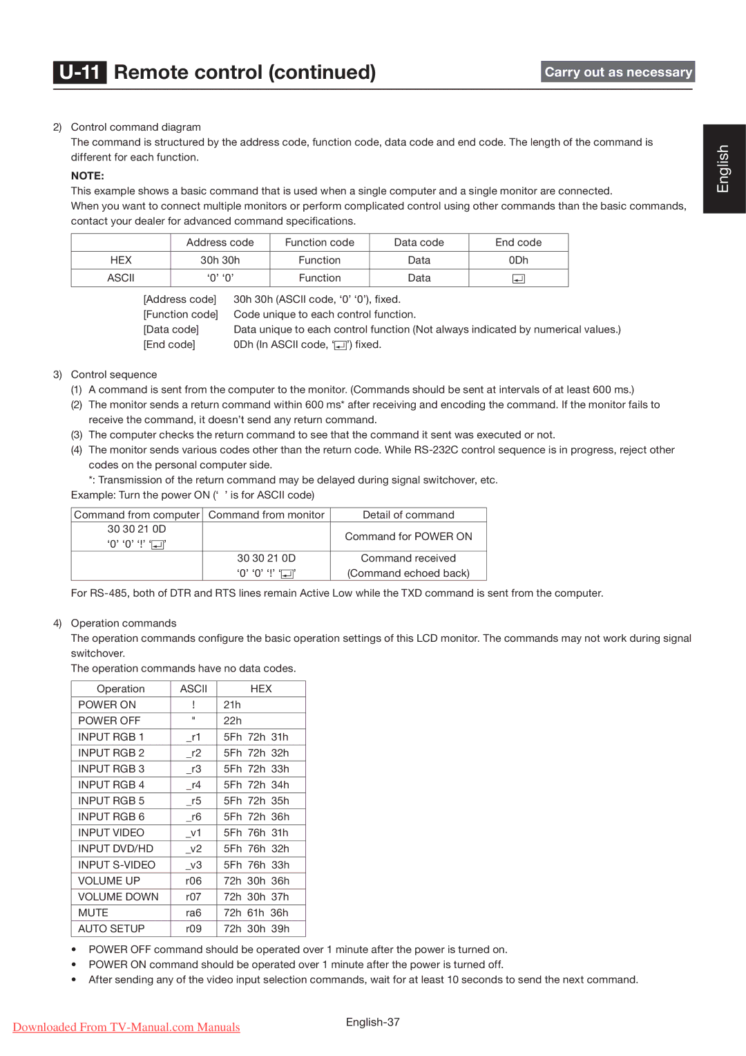
4)Operation commands
The operation commands configure the basic operation settings of this LCD monitor. The commands may not work during signal switchover.
The operation commands have no data codes.
Operation | ASCII |
| HEX | |
|
|
|
|
|
POWER ON | ! | 21h |
|
|
|
|
|
|
|
POWER OFF | " | 22h |
|
|
|
|
|
| |
INPUT RGB 1 | _r1 | 5Fh 72h | 31h | |
|
|
| ||
INPUT RGB 2 | _r2 | 5Fh 72h 32h | ||
|
|
|
| |
INPUT RGB 3 | _r3 | 5Fh 72h | 33h | |
|
|
|
| |
INPUT RGB 4 | _r4 | 5Fh 72h | 34h | |
|
|
|
| |
INPUT RGB 5 | _r5 | 5Fh 72h | 35h | |
|
|
|
| |
INPUT RGB 6 | _r6 | 5Fh 72h | 36h | |
|
|
|
| |
INPUT VIDEO | _v1 | 5Fh 76h | 31h | |
|
|
|
| |
INPUT DVD/HD | _v2 | 5Fh 76h | 32h | |
|
|
|
| |
INPUT | _v3 | 5Fh 76h | 33h | |
|
|
|
|
|
VOLUME UP | r06 | 72h | 30h | 36h |
|
|
|
|
|
VOLUME DOWN | r07 | 72h | 30h | 37h |
|
|
|
| |
MUTE | ra6 | 72h | 61h 36h | |
|
|
|
|
|
AUTO SETUP | r09 | 72h | 30h | 39h |
|
|
|
|
|
•POWER OFF command should be operated over 1 minute after the power is turned on.
•POWER ON command should be operated over 1 minute after the power is turned off.
•After sending any of the video input selection commands, wait for at least 10 seconds to send the next command.
English
Downloaded From | |
|