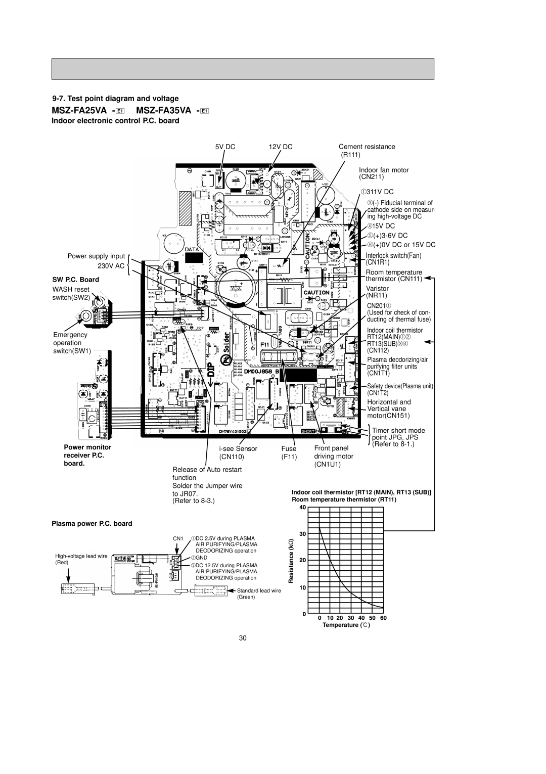
9-7. Test point diagram and voltage
MSZ-FA25VA - E1
MSZ-FA35VA - E1
Indoor electronic control P.C. board
Power supply input 230V AC {
SW P.C. Board
WASH reset switch(SW2) ![]()
Emergency operation switch(SW1)
5V DC | 12V DC | Cement resistance | ||||
|
| (R111) | ||||
|
| Indoor fan motor | ||||
|
| (CN211) | ||||
|
| 1311V DC | ||||
|
| |||||
|
| cathode side on measur- | ||||
|
| ing | ||||
|
| 415V DC | ||||
|
| |||||
|
| 6(+)0V DC or 15V DC | ||||
|
| Interlock switch(Fan) | ||||
|
| (CN1R1) | ||||
|
| Room temperature | ||||
|
| thermistor (CN111) |
|
| ||
|
|
| ||||
|
| Varistor | ||||
|
| (NR11) | ||||
|
| CN2011 | ||||
|
| (Used for check of con- | ||||
|
| ducting of thermal fuse) | ||||
|
| Indoor coil thermistor | ||||
|
| RT12(MAIN)12 | ||||
|
| RT13(SUB)34 |
|
|
|
|
|
|
|
| |||
|
| (CN112) | ||||
|
| Plasma deodorizing/air | ||||
|
| purifying filter units | ||||
|
| (CN1T1) | ||||
|
| Safety device(Plasma unit) | ||||
|
| (CN1T2) | ||||
|
| Horizontal and | ||||
|
| Vertical vane | ||||
|
| motor(CN151) | ||||
Power monitor receiver P.C. board.
Release of Auto restart function
Solder the Jumper wire
to JR07. (Refer to
|
| } |
|
| Timer short mode |
|
| point JPG, JPS |
Fuse | Front panel | (Refer to |
| ||
(F11) | driving motor |
|
| (CN1U1) |
|
Indoor coil thermistor [RT12 (MAIN), RT13 (SUB)] Room temperature thermistor (RT11)
Plasma power P.C. board
CN1 1DC 2.5V during PLASMA AIR PURIFYING/PLASMA DEODORIZING operation
 2GND
2GND
![]() 3DC 12.5V during PLASMA AIR PURIFYING/PLASMA DEODORIZING operation
3DC 12.5V during PLASMA AIR PURIFYING/PLASMA DEODORIZING operation
![]() Standard lead wire (Green)
Standard lead wire (Green)
Resistance (k")
Temperature (:)
30