| OPERATING PROCEDURE | PHOTOS |
| |
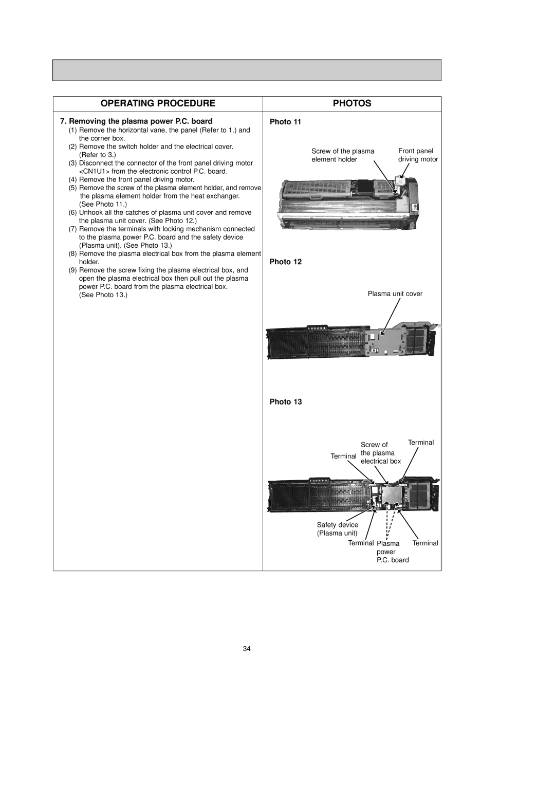
7. Removing the plasma power P.C. board | Photo 11 |
| ||
(1) | Remove the horizontal vane, the panel (Refer to 1.) and |
|
| |
| the corner box. |
|
| |
(2) | Remove the switch holder and the electrical cover. | Screw of the plasma | Front panel | |
| (Refer to 3.) | |||
| element holder | driving motor | ||
(3) | Disconnect the connector of the front panel driving motor | |||
|
| |||
| <CN1U1> from the electronic control P.C. board. |
|
| |
(4) | Remove the front panel driving motor. |
|
| |
(5)Remove the screw of the plasma element holder, and remove the plasma element holder from the heat exchanger.
(See Photo 11.)
(6)Unhook all the catches of plasma unit cover and remove the plasma unit cover. (See Photo 12.)
(7)Remove the terminals with locking mechanism connected to the plasma power P.C. board and the safety device (Plasma unit). (See Photo 13.)
(8)Remove the plasma electrical box from the plasma element
holder. | Photo 12 |
(9)Remove the screw fixing the plasma electrical box, and open the plasma electrical box then pull out the plasma
power P.C. board from the plasma electrical box. | Plasma unit cover |
(See Photo 13.) |
Photo 13
| Screw of | Terminal |
|
| |
Terminal | the plasma |
|
| electrical box |
|
Safety device (Plasma unit)
Terminal Plasma | Terminal |
power |
|
P.C. board |
|
34