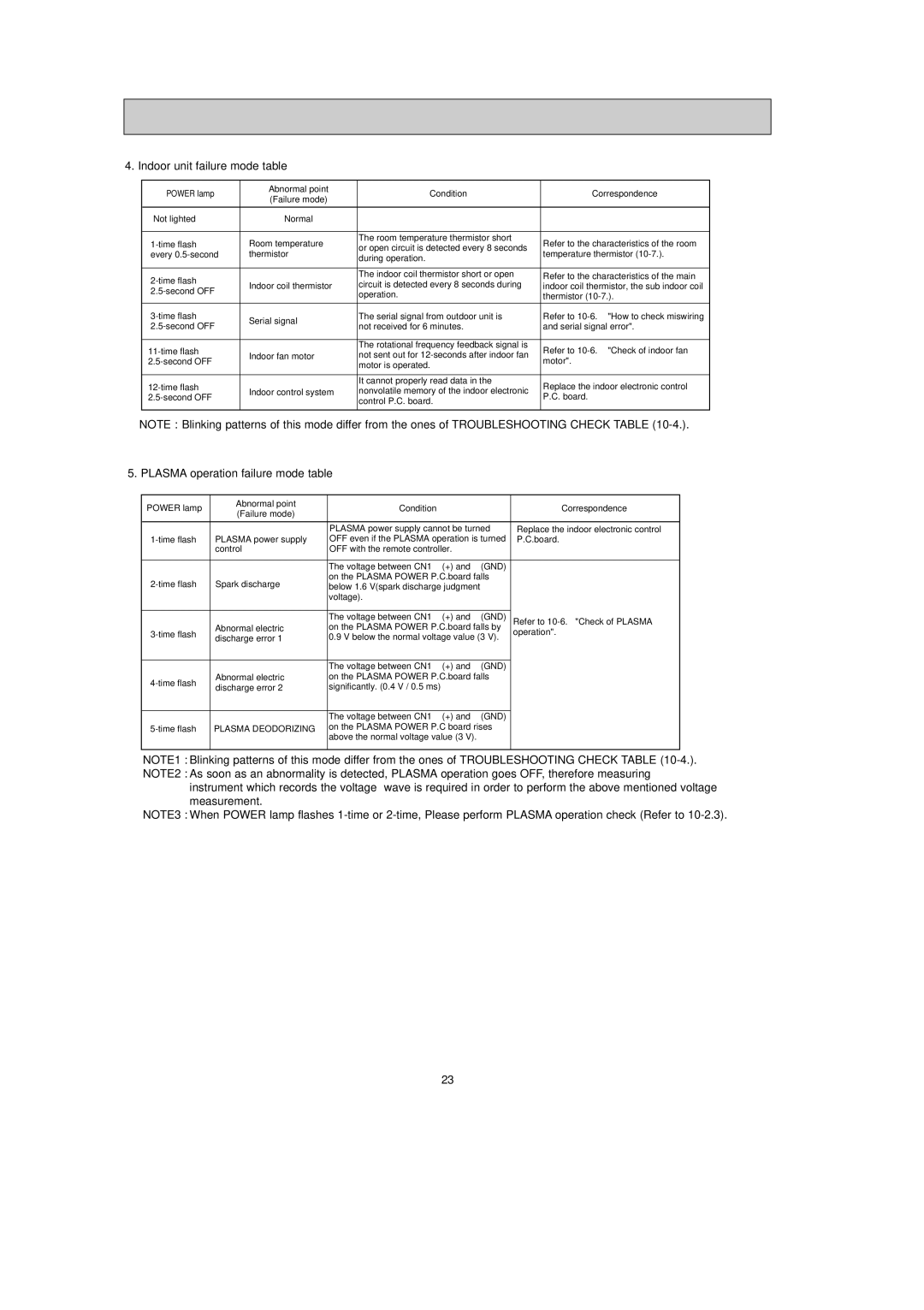
4. Indoor unit failure mode table
POWER lamp | Abnormal point | Condition | Correspondence | |
(Failure mode) | ||||
|
|
| ||
|
|
|
| |
Not lighted | Normal | — | — | |
|
|
|
| |
Room temperature | The room temperature thermistor short | Refer to the characteristics of the room | ||
or open circuit is detected every 8 seconds | ||||
every | thermistor | temperature thermistor | ||
during operation. | ||||
|
|
| ||
|
|
|
| |
| The indoor coil thermistor short or open | Refer to the characteristics of the main | ||
Indoor coil thermistor | circuit is detected every 8 seconds during | indoor coil thermistor, the sub indoor coil | ||
| operation. | thermistor | ||
|
| |||
|
|
|
| |
Serial signal | The serial signal from outdoor unit is | Refer to | ||
not received for 6 minutes. | and serial signal error". | |||
| ||||
|
|
|
| |
| The rotational frequency feedback signal is | Refer to | ||
Indoor fan motor | not sent out for | |||
motor". | ||||
| motor is operated. | |||
|
|
| ||
|
|
|
| |
| It cannot properly read data in the | Replace the indoor electronic control | ||
Indoor control system | nonvolatile memory of the indoor electronic | |||
P.C. board. | ||||
| control P.C. board. | |||
|
|
| ||
|
|
|
|
NOTE : Blinking patterns of this mode differ from the ones of TROUBLESHOOTING CHECK TABLE
5. PLASMA operation failure mode table
POWER lamp | Abnormal point | Condition | Correspondence | |
(Failure mode) | ||||
|
|
| ||
|
|
|
| |
|
| PLASMA power supply cannot be turned | Replace the indoor electronic control | |
PLASMA power supply | OFF even if the PLASMA operation is turned | P.C.board. | ||
| control | OFF with the remote controller. |
| |
|
|
|
| |
|
| The voltage between CN1 3(+) and 2(GND) |
| |
Spark discharge | on the PLASMA POWER P.C.board falls |
| ||
below 1.6 V(spark discharge judgment |
| |||
|
| voltage). |
| |
|
|
|
| |
| Abnormal electric | The voltage between CN1 3(+) and 2(GND) | Refer to | |
on the PLASMA POWER P.C.board falls by | operation". | |||
discharge error 1 | 0.9 V below the normal voltage value (3 V). | |||
| ||||
|
|
|
| |
|
| The voltage between CN1 3(+) and 2(GND) |
| |
Abnormal electric | on the PLASMA POWER P.C.board falls |
| ||
discharge error 2 | significantly. (0.4 V / 0.5 ms) |
| ||
|
| |||
|
|
|
| |
|
| The voltage between CN1 3(+) and 2(GND) |
| |
PLASMA DEODORIZING | on the PLASMA POWER P.C board rises |
| ||
|
| above the normal voltage value (3 V). |
| |
|
|
|
|
NOTE1 : Blinking patterns of this mode differ from the ones of TROUBLESHOOTING CHECK TABLE
NOTE2 : As soon as an abnormality is detected, PLASMA operation goes OFF, therefore measuring instrument which records the voltage wave is required in order to perform the above mentioned voltage measurement.
NOTE3 : When POWER lamp flashes
23
